
Think you might need a different torch as the gas has to exit around the tip.
Alan
Robsey's Thread of Random Ramblings.
Moderator: Robsey

Re: Robsey's Thread of Random Ramblings.
just had a check,
It would probably need a complete torch assembly as I cannot see a gas hose within the torch assembly, although I could see a few exit holes behind the nozzle tip.
saying that though - I do not know anything about welders, other than how to set them up, turn them on, change the feed rate and set the power rating to suit metal thickness.
Never looked inside the main casing as it is screwed shut.
-
thomas

- Registered user
- Posts: 227
- Joined: Sat Dec 31, 2011 11:18 pm
- Location: Roxburghshire, Scotland
Re: Robsey's Thread of Random Ramblings.
Another way is to look for a torch that has a manual gas valve incorporated in the switch/trigger, possibly from the 'with gas' version of the same or similar mig. The torch you have may have parts in common with the 'with gas' models. You would not then need a gas valve/solenoid.Robsey wrote: ↑Sun Jun 19, 2022 1:59 pm Thanks -
I have been looking online, and it appears to be quite easy to convert my welder from gasless to MIG.
General gist is to reverse the polarity of the earth clamp and torch connections.
Plumb in an electronic gas valve.
And connect a gas bottle and regulator.
Not sure if I need to change the tip of the torch too.
But it all looks doable for a modestly manageable outlay.
If you twist/pull off the shroud from the end of the torch and there are circumferential holes above the screw in tip, chances are that is common to the other models and potentially usable with gas.
In the SIP mig I've got one gas solenoid is 24V DC operated and the other is 12V DC, just by happenstance. Prefer not to have mains voltages inside the wire-feed compartment where they're located. To further complicate matters SOL1 has to be on first before SOL2 can be turned on.
Solenoids through-hole mounted to the outside (1st pic) with longish external/inlet stubs seem the easiest type to incorporate as a mod to an existing machine. There are those that mount using two screws (2nd pic). Can be 240VAC, or 24VDC or whatever, depends what you have in the machine that you can tap into that provides a supply when wirefeed or contactor or both together are turned on. Sort the plumbing up to the torch out, the electrical part of it can usually be solved trivially.


--
Cav 1994 1.8LSi 5-dr Jungle Green Pearl: Daily.
Cav 1994 1.8LSi 5-dr Jungle Green Pearl: Daily.
Re: Robsey's Thread of Random Ramblings.
I have just had a "What the actual Fxxx" moment.
I defy you to work this one out.
Locked the house door from the outside when I left for the unit last night -
As usual, put the key in boot of car - out of sight.
Got home last night, no sign.
Spent a good 20 minutes searching my pockets and the whole car. - all to no avail.
Had to phone the other half to get her to let me in.
Missus had to use her key to unlock the door (obviously).
She was major pi$$ed at being woken up at 2:00am.
Got up this morning to go to work, and the house key was on my work bag in the house.
Laid out on top, in plain view.
How does that work?
It has really screwed up my brain.
Re: Robsey's Thread of Random Ramblings.
Have you been on the booze again 


Re: Robsey's Thread of Random Ramblings.
Your wife probably sat it on the bag because you done a "man search" for it
David
Re: Robsey's Thread of Random Ramblings.
You have obviously met my wife - that sounds just like what she would do.
But not on this occasion.
Nope - there is nothing at all that can explain the mystery of the self-relocating house keys.
But not on this occasion.
Nope - there is nothing at all that can explain the mystery of the self-relocating house keys.
Re: Robsey's Thread of Random Ramblings.
Latest project...
A wiring harness for a fridge in a VW Crafter High Top, Long Wheel Base camper van.
Not mine obviously...
It belongs to my Clinical Lead.
She has reported problems with her Dometic CRX fridge not working.
All the relevant lights come on, but it simply does not cool down.
There is the flashing orange sensor-fault light, but I believe that is a red herring.

After a lot of googling, I discovered that the biggest issue is with the power feed cables being too thin to carry adequate current, or resulting in excessive losses over the 3 metre cable distance from the leisure battery.
All very odd as it has a 15amp inline blade fuse.
Further research found that a company makes beefier cables to cure this problem.
The company quotes 6mm csa cable...
To bring this into perspective - the fusebox to ignition switch feed on my T25 is only 4mm CSA, and that feeds everything on the van.
Except the starter, which has 6mm csa cabling to minimise losses over the 4 metre cable run;
and the main starter battery to fuse box cable which is also 6mm csa.
Anyway - as with many items at the moment, they are currently out of stock.
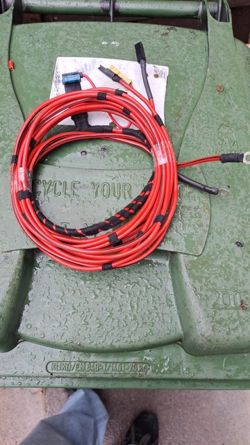
So - Rob to the rescue..
It is really very simple.
3 metre long cable - 8mm eyelet at one end and a sturdy female spade and insulator at the other end.
The positive cable has a 15 amp fuse at the battery endand a little male spade tail at the fridge end for a fan to connect to.
Due to the thickness, I used a gas ring on my cooker to heat the cables enough for the connectors to be soldered effectively.
I always crimp, solder and heat-shrink tube all my wiring.
On heavy stuff, good insulation and security is imperative.
The real test will be on Friday when we test my loom and see if it sorts her fridge issue.
Fingers crossed.
I have mentioned that I am not a fan of the connector block that the conversion company installed for the previous owner.
A bit rough, but I suppose it fulfils a need.
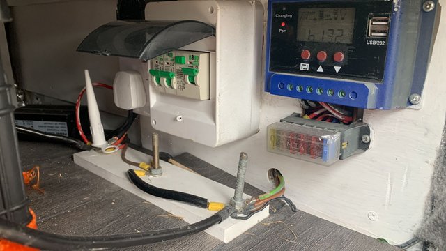
I suspect using the middle post and a link cable to the right-hand post for the negative rail will not help either.
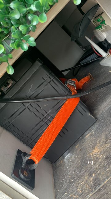
And the leisure battery - strapped back, rather than clamped in situ.
A wiring harness for a fridge in a VW Crafter High Top, Long Wheel Base camper van.
Not mine obviously...
It belongs to my Clinical Lead.
She has reported problems with her Dometic CRX fridge not working.
All the relevant lights come on, but it simply does not cool down.
There is the flashing orange sensor-fault light, but I believe that is a red herring.
After a lot of googling, I discovered that the biggest issue is with the power feed cables being too thin to carry adequate current, or resulting in excessive losses over the 3 metre cable distance from the leisure battery.
All very odd as it has a 15amp inline blade fuse.
Further research found that a company makes beefier cables to cure this problem.
The company quotes 6mm csa cable...
To bring this into perspective - the fusebox to ignition switch feed on my T25 is only 4mm CSA, and that feeds everything on the van.
Except the starter, which has 6mm csa cabling to minimise losses over the 4 metre cable run;
and the main starter battery to fuse box cable which is also 6mm csa.
Anyway - as with many items at the moment, they are currently out of stock.
So - Rob to the rescue..
It is really very simple.
3 metre long cable - 8mm eyelet at one end and a sturdy female spade and insulator at the other end.
The positive cable has a 15 amp fuse at the battery endand a little male spade tail at the fridge end for a fan to connect to.
Due to the thickness, I used a gas ring on my cooker to heat the cables enough for the connectors to be soldered effectively.
I always crimp, solder and heat-shrink tube all my wiring.
On heavy stuff, good insulation and security is imperative.
The real test will be on Friday when we test my loom and see if it sorts her fridge issue.
Fingers crossed.
I have mentioned that I am not a fan of the connector block that the conversion company installed for the previous owner.
A bit rough, but I suppose it fulfils a need.
I suspect using the middle post and a link cable to the right-hand post for the negative rail will not help either.
And the leisure battery - strapped back, rather than clamped in situ.
Re: Robsey's Thread of Random Ramblings.
May I suggest testing the fridge with a 6 pack inside then you will have something to celebrate with!
Alan
Alan
Re: Robsey's Thread of Random Ramblings.
I love the idea, but I haven't consumed 'any' beer since approx 2008.
Besides - it isn't my fridge - lol.
Besides - it isn't my fridge - lol.
-
ilovedmymantas

- Registered user
- Posts: 1202
- Joined: Sat Jan 12, 2013 2:54 am
Re: Robsey's Thread of Random Ramblings.
I've every confidence it will work, you know your stuff.Robsey wrote: ↑Wed Jul 27, 2022 7:34 pmThe real test will be on Friday when we test my loom and see if it sorts her fridge issue.
Fingers crossed.
I have mentioned that I am not a fan of the connector block that the conversion company installed for the previous owner.
A bit rough, but I suppose it fulfils a need.
I suspect using the middle post and a link cable to the right-hand post for the negative rail will not help either.
And the leisure battery - strapped back, rather than clamped in situ.
A bit rough is extremely flattering, that's a 1970's diy type improvisation - 'go and find me coach bolts, the longer the better, and a bit of wood son - you found three? Great, let's use them all!'
A silicon nozzle for insulation, bolts long enough to add forty more connections, crude at best. I'm surprised a conversion company would do this,
it looks very amateurish.
I'm ok with a strapped leisure battery - if it's done correctly.
This one isn't to me. The anchor point is too far from the edge of the battery and too low down. It should be three-quarters up the battery parallel not a third up
" It's not rust. It's age-related patina " 
1980 vauxhall cavalier MK1 1.6L, 1982 opel manta berlinetta 1.8s, 1985 opel manta 2.0 gte, 1990 cavalier 2.0 gl ,1994 cavalier sri x20xev
-1995 cdx x20xev
---------------
Matt
1980 vauxhall cavalier MK1 1.6L, 1982 opel manta berlinetta 1.8s, 1985 opel manta 2.0 gte, 1990 cavalier 2.0 gl ,1994 cavalier sri x20xev
-1995 cdx x20xev
---------------
Matt
Re: Robsey's Thread of Random Ramblings.
It is mainly guesswork on my behalf.
I have fitted 8mm eyelets in place of the previous 6mm eyelets.
All soldered and sleeved for a lasting solution.
I have some cable sleeving somewhere, just to provide a better form of insulation rather than a mastic gun nozzle.
I defy anyone who can find an online source of info for locating, testing or replacing a temperature sensor in one of these CRX fridges.
This is why I think it is a red herring.
Tomorrow will prove me right or wrong, I suppose.
Re: Robsey's Thread of Random Ramblings.
I fitted 6mm cables, and it is working perfectly.
Compressor and temperature leds are blue.
No nasty orange - pah!
Phew!!
Wired directly to the leisure battery via the recommended 15amp fuse.
Fuse very close to the battery.
There was a 10amp fuse in the "speaker wire" size cables fitted by the initial installer.
It looks like it is "factory spec" judging by how it is tied back tidily to the rest of the fridge cabinet.
Oddly the 10amp fuse was at the fridge end, not the battery end.
Obviously some people have no idea about basic electrics.
So - all good
Lets hope she does not break anything else.
Seems to be a lot of plain painted plywood panels all along the offside van walls with everything attached to them.
I think the current owner is the third since the conversion / fitting of the camper parts, c/w awning, solar panel, distribution board and 3-way electrical hook-up / charge system.
Thankfully there is venting under both the gas bottle and the fridge.
Other than looking amatuerish, it does now all work as it should.
I will point out, that I did not dig any deeper than necessary to fix the fridge issue.
I am bound to find something else that would make me feel a bit nervous if I was the owner.
Compressor and temperature leds are blue.
No nasty orange - pah!
Phew!!
Wired directly to the leisure battery via the recommended 15amp fuse.
Fuse very close to the battery.
There was a 10amp fuse in the "speaker wire" size cables fitted by the initial installer.
It looks like it is "factory spec" judging by how it is tied back tidily to the rest of the fridge cabinet.
Oddly the 10amp fuse was at the fridge end, not the battery end.
Obviously some people have no idea about basic electrics.
So - all good
Lets hope she does not break anything else.
Yes - definitely a "Bodgit & Scarper" job.ilovedmymantas wrote: ↑Thu Jul 28, 2022 1:48 am I'm surprised a conversion company would do this,
it looks very amateurish.
Seems to be a lot of plain painted plywood panels all along the offside van walls with everything attached to them.
I think the current owner is the third since the conversion / fitting of the camper parts, c/w awning, solar panel, distribution board and 3-way electrical hook-up / charge system.
It appears to be the same method used as for the gas bottle under the sink, next to the fridge.ilovedmymantas wrote: ↑Thu Jul 28, 2022 1:48 am I'm ok with a strapped leisure battery - if it's done correctly.
This one isn't to me. The anchor point is too far from the edge of the battery and too low down. It should be three-quarters up the battery parallel not a third up
Thankfully there is venting under both the gas bottle and the fridge.
Other than looking amatuerish, it does now all work as it should.
I will point out, that I did not dig any deeper than necessary to fix the fridge issue.
I am bound to find something else that would make me feel a bit nervous if I was the owner.
Re: Robsey's Thread of Random Ramblings.
It may sound like my camper van thread has been a bit quiet recently, but I am actually doing more hours than before.
Two evenings per week, which is much better than 2 1/2 hours per month in August and September.
Anyway - doing more of a partnership effort with Troy.
In otherwords, I do some jobs on vehicles for Troy, and in return, he will do some welding on the van.
Recent jobs have been:-
Rebuild / Swap the guts on a motorcycle fuel tank lock.
To save him a fiddly job. Five low-flying springs to add to the fun.
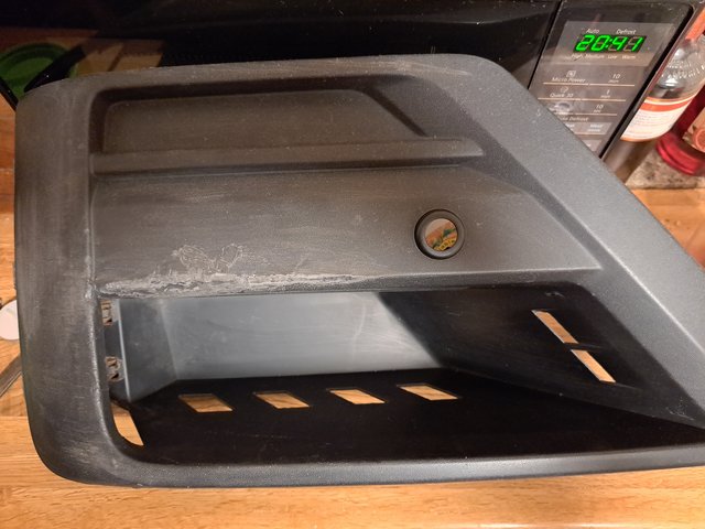
Next - prepare the painted bumper panel for a crafter van to remove scuffs and key the surface for a fresh paint job.
Next - rebuild the bumper inserts. one of which was literally torn apart. I managed to reform this with careful heating followed by a bit of plastic welding to close up a lot of the splits.
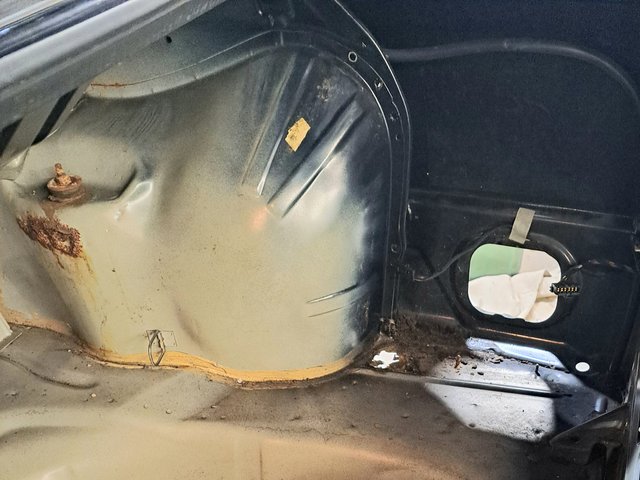
This last week, I did some work on his pride and joy, so I am obviously trusted.
This comprised completely cutting out his offside inner wing / wheel arch so that I could separate out his suspension turret.
Followed by making up two repair patches for the rear valance.
After that, I started making repair patches for the passenger footwell on my van.
Two evenings per week, which is much better than 2 1/2 hours per month in August and September.
Anyway - doing more of a partnership effort with Troy.
In otherwords, I do some jobs on vehicles for Troy, and in return, he will do some welding on the van.
Recent jobs have been:-
Rebuild / Swap the guts on a motorcycle fuel tank lock.
To save him a fiddly job. Five low-flying springs to add to the fun.
Next - prepare the painted bumper panel for a crafter van to remove scuffs and key the surface for a fresh paint job.
Next - rebuild the bumper inserts. one of which was literally torn apart. I managed to reform this with careful heating followed by a bit of plastic welding to close up a lot of the splits.
This last week, I did some work on his pride and joy, so I am obviously trusted.
This comprised completely cutting out his offside inner wing / wheel arch so that I could separate out his suspension turret.
Followed by making up two repair patches for the rear valance.
After that, I started making repair patches for the passenger footwell on my van.
Re: Robsey's Thread of Random Ramblings.
I have been quiet on this thread for a while... still been bumbling along with various things.
Things have been quite busy on the unit front...
Multiple jobs on the go at present.
Recent work has been body repairs on a Cavalier, coming to a thread near you soon.

Now drawing to a close, but it has given me the mental boost to start preparing to fix my own Cavalier.
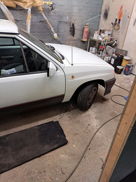
There was also a Nova...
New wings, side repeaters and aerial to fit.
Not too shabby if you ask me.
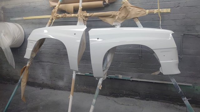
As usual, I left the bodywork to the expert, I just assisted with the fiddley bits...
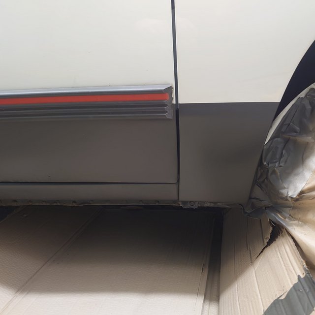
Current job is....
Well, lets see if any clever clogs can spot the car...
Or what is left of it.

The car has been stripped for a full respray.
As usual, I volunteered for the fiddley annoying jobs, whilst Troy does the precision stuff.
On this car, there is something called a 'belt line'.
This needs to be removed to allow a proper paint job.
The issue here is the need to remove the soft-top, and then a rain guard from the rear of the cockpit.
Thirteen 10mm nuts (M6) across the curved periphery followed by countless trim clips, four peg bolts and six 14mm nuts to get the soft-top out.
Followed by another eight 10mm nuts to remove the belt line. About an hour, all in.
Quite a respectable time.

Next job to get the alternator out.
Something sounds really rough, and the engine felt very tight during cranking.
A couple of hours moving an engine mount and trying to loosen the alternator bolt ensued.
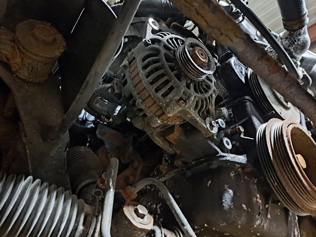
Eventually the bolt loosened, but not before shearing off it's tip.
It is assumed the previous owner's mechanic had tried to knock the bolt through resulting in a peened over thread, no way that was coming out, without drilling...
My job for tomorrow night no doubt.
Not sure what it is on this model, but the engines all look like a mass of rust, and white powdery aluminium oxide.
We have come to the conclusion that it is the water pump, not the alternator causing the roughness.
There is some water seapage at the front of the engine.
Looking at how rubbish the previous garage must have been, the plan is to do a full timing belt and tensioner change - along with a new water pump.
Things have been quite busy on the unit front...
Multiple jobs on the go at present.
Recent work has been body repairs on a Cavalier, coming to a thread near you soon.
Now drawing to a close, but it has given me the mental boost to start preparing to fix my own Cavalier.
There was also a Nova...
New wings, side repeaters and aerial to fit.
Not too shabby if you ask me.
As usual, I left the bodywork to the expert, I just assisted with the fiddley bits...
Current job is....
Well, lets see if any clever clogs can spot the car...
Or what is left of it.
The car has been stripped for a full respray.
As usual, I volunteered for the fiddley annoying jobs, whilst Troy does the precision stuff.
On this car, there is something called a 'belt line'.
This needs to be removed to allow a proper paint job.
The issue here is the need to remove the soft-top, and then a rain guard from the rear of the cockpit.
Thirteen 10mm nuts (M6) across the curved periphery followed by countless trim clips, four peg bolts and six 14mm nuts to get the soft-top out.
Followed by another eight 10mm nuts to remove the belt line. About an hour, all in.
Quite a respectable time.
Next job to get the alternator out.
Something sounds really rough, and the engine felt very tight during cranking.
A couple of hours moving an engine mount and trying to loosen the alternator bolt ensued.
Eventually the bolt loosened, but not before shearing off it's tip.
It is assumed the previous owner's mechanic had tried to knock the bolt through resulting in a peened over thread, no way that was coming out, without drilling...
My job for tomorrow night no doubt.
Not sure what it is on this model, but the engines all look like a mass of rust, and white powdery aluminium oxide.
We have come to the conclusion that it is the water pump, not the alternator causing the roughness.
There is some water seapage at the front of the engine.
Looking at how rubbish the previous garage must have been, the plan is to do a full timing belt and tensioner change - along with a new water pump.
Re: Robsey's Thread of Random Ramblings.
More work on the black soft top tonight...
First job, loosen the road wheel nuts, jack up the car and place on axle-stands.
Then nuts and wheels off.
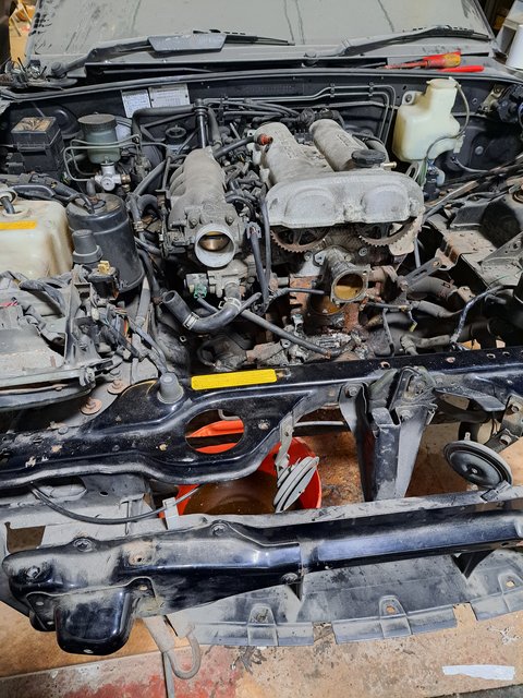
Intended plan for tonight - to finish removing the alternator.
This required draining the coolant, the removal of the radiator and lowering of the anti-roll bar from the chassis so that I had a clear line to drill out the remnants of the old bolt.
Due the tightness of the engine and an apparent water leak, we concluded a potential water-pump issue.
What a total nightmare to remove the water-pump.
The timing belt had to come off, along with a rear pulley cover, which in turn needed the cam-shaft sprockets removing
Oh lordy!!!
In conclusion three hours of engine stripping left us with this....
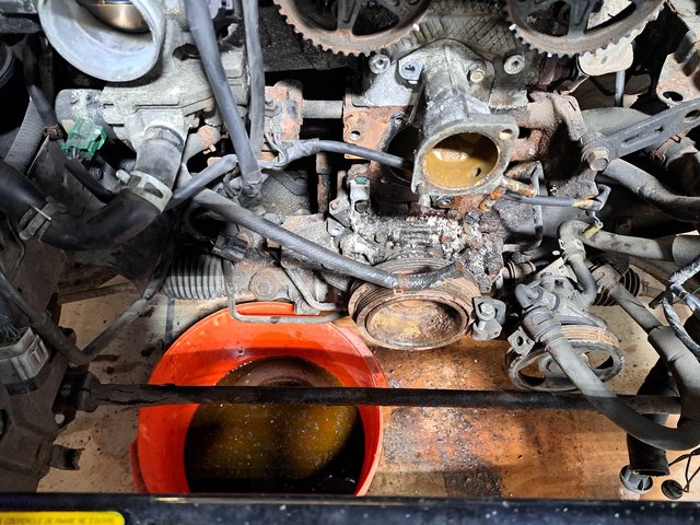
Oddly, with the belts removed, we could not feel any roughness in any of the bearings. Just a bit of noise on the exhaust side belt roller and the water-pump.
The water pump is fitted within a huge casting covering about 1/3 of the front of the engine block.
Plan next week is to fit a replacement starter motor along with a timing belt kit and water-pump assembly.
Should be good fun
First job, loosen the road wheel nuts, jack up the car and place on axle-stands.
Then nuts and wheels off.
Intended plan for tonight - to finish removing the alternator.
This required draining the coolant, the removal of the radiator and lowering of the anti-roll bar from the chassis so that I had a clear line to drill out the remnants of the old bolt.
Due the tightness of the engine and an apparent water leak, we concluded a potential water-pump issue.
What a total nightmare to remove the water-pump.
The timing belt had to come off, along with a rear pulley cover, which in turn needed the cam-shaft sprockets removing
Oh lordy!!!
In conclusion three hours of engine stripping left us with this....
Oddly, with the belts removed, we could not feel any roughness in any of the bearings. Just a bit of noise on the exhaust side belt roller and the water-pump.
The water pump is fitted within a huge casting covering about 1/3 of the front of the engine block.
Plan next week is to fit a replacement starter motor along with a timing belt kit and water-pump assembly.
Should be good fun
-
James McGrath

- Club Admin
- Posts: 2896
- Joined: Tue Aug 11, 2009 11:35 am
- Location: East Sussex
Re: Robsey's Thread of Random Ramblings.
Have you been talking to Troy? - lol
Yep, it is his partners next toy...for this summer.
A Miata in yank-land.
Bought as another project with front end crash damage a few years ago.
Front rebuilt and then left to collect dust.
Until now...
It is a real work out for the brain. Every time we start on a different make or model, you have to learn a new way of thinking.
To work out what the manufacturer was thinking when they designed the car.
-
James McGrath
- Club Admin
- Posts: 2896
- Joined: Tue Aug 11, 2009 11:35 am
- Location: East Sussex
Re: Robsey's Thread of Random Ramblings.
I couldn't tell you what generation mx5 it is!
Re: Robsey's Thread of Random Ramblings.
It is a mk1 - you can tell by the bug-eye pop-up headlamps.
1997 (R reg).
UPDATE - After this week, my Thursday night jaunts are moving to Friday night.
Recently motorway traffic is a nightmare, so I am having to get up and go to work an hour earlier.
I have my own Rehabilitation Engineer clinic every Friday - all day
At least on a Saturday morning, it doesn't matter if I get up late.
Re: Robsey's Thread of Random Ramblings.
Tonight's challenge...
My Samsung washing machine suddenly stopped on my 2nd wash of the day.
The kitchen plunged into idylic quietness.
Obviously I didn't think anything of it.
I like peace and quiet - I am getting old and irritable.
But a trip to make a brew a little while later....
And I happened upon a defunct washer.
'IE' on the display told me that something wasn't right.
I looked in the owners manual on my phone...
Yes I have all my household appliance manuals on my phone, just in case.
Strange 'IE' is not listed in the fault code list...
Looking online mentions water inlet blockage.
I am a veteran at stripping down this washer...
I replaced the drum, and two dampers a few years ago.
So removing the lid to access the inlet valves was a doddle.
I cleaned every hose on the machine, including drainage pipes. Nothing of note in there.
That is when I noticed a snapped pressure sensor wire.
The sensor had fallen off it's mount and had been tossed about by the movement of the drum at 1400 rpm.
It had snapped off its mount due to many years of vibration and shaking.
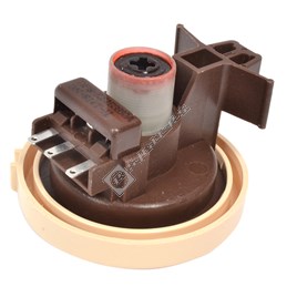
I re-made the wiring from the sensor to the machine loom.
3 wires - orange, pink, and yellow.
I used a spare car radio ISO plug to mount the new connector pins.
Re-connected it all up - tada... success.
A free fix - my favourite type.
My Samsung washing machine suddenly stopped on my 2nd wash of the day.
The kitchen plunged into idylic quietness.
Obviously I didn't think anything of it.
I like peace and quiet - I am getting old and irritable.
But a trip to make a brew a little while later....
And I happened upon a defunct washer.
'IE' on the display told me that something wasn't right.
I looked in the owners manual on my phone...
Yes I have all my household appliance manuals on my phone, just in case.
Strange 'IE' is not listed in the fault code list...
Looking online mentions water inlet blockage.
I am a veteran at stripping down this washer...
I replaced the drum, and two dampers a few years ago.
So removing the lid to access the inlet valves was a doddle.
I cleaned every hose on the machine, including drainage pipes. Nothing of note in there.
That is when I noticed a snapped pressure sensor wire.
The sensor had fallen off it's mount and had been tossed about by the movement of the drum at 1400 rpm.
It had snapped off its mount due to many years of vibration and shaking.
I re-made the wiring from the sensor to the machine loom.
3 wires - orange, pink, and yellow.
I used a spare car radio ISO plug to mount the new connector pins.
Re-connected it all up - tada... success.
A free fix - my favourite type.
Re: Robsey's Thread of Random Ramblings.
Oh my lordy...
I think I have found one of the trickiest jobs to do on this Mazda.
The starter motor
Two of the bolts are accessed by squeezing in between the bell housing and the firewall in the engine bay.
Troy tells me that I have large hands, and that is why I struggle with jobs like this.
Either way, approx 2 1/2 hours to get the starter off.
I started to put the replacement starter in, but it was not playing ball.
So it is likely that I will be spending Tuesday fiting the starter.
Re: Robsey's Thread of Random Ramblings.
A new project idea - retro-fitting LED wheelchair lights to the wife's powered wheelchair.
The tricky bit is - the make and configuration is totally different to that of the wife's wheelchair.
Neither her joystick nor power module are compatible.
Mechanically, the lights would fit anything.
Simple M6 bolt-on job.
Now then for the electrinics.
All chairs are 24v ( 2 × 12v batteries).
The led lights are 12 volts
There are 4 light units
2 (front) with a white led and an orange led,
And of course
2 (rear) with a red led and an orange led.
White and red lights can be wired up, so that each side is wired up to one battery.
Battery 1 for the left,
battery 2 for the right.
Double throw switch and fuses - sorted.
--------‐----------------------‐------------
Now then for the indicators.
Most chairs work via a pair of switches on the controller.
Hmm - none on her panel.
I know, let's make them automated!!
In a similar way to a tracked vehicle when turning, wheelchairs work as follows: -
(We are talking powered chair, not a mobility scooter with handle-bars).
One motor runs forwards, and the other goes in reverse.
Can you see the way mine brain is working?
When turning right, the right motor goes backwards...
Hmm - motor voltage (polarity) is reversed.
So if I tap into the motor-wire that is +24volts when going backwards, I can use this to trigger a relay for the indicator on that side.
Go one stage further, and use a daytime running light idea.
Use the relay to kill the head / tail light on that side, and illuminate the indicators instead.
It is possible to use a 24v relay controlled by each motor feed, to switch a 12v bulb control circuit. - genius.
The 24v feed is only live when the chair is on AND the motor is going backwards.
And the 12v feeds are only on if the lights are turned on.
Here is my idea...
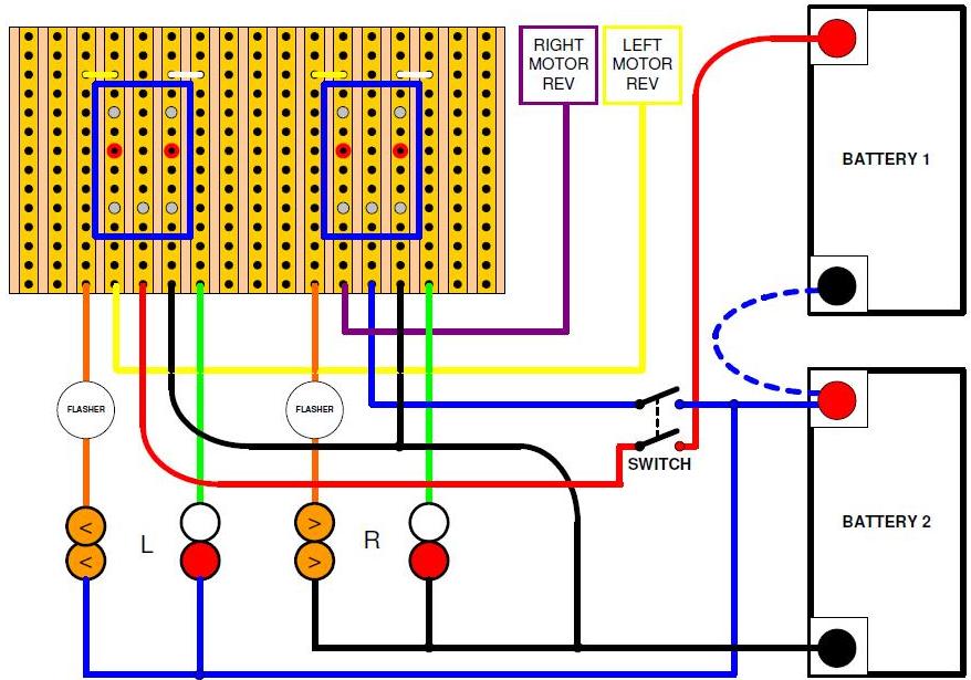
As an added bonus - if driving backwards, all indicators will be flashing...
Instart hazard warning lights - lol.
The tricky bit is - the make and configuration is totally different to that of the wife's wheelchair.
Neither her joystick nor power module are compatible.
Mechanically, the lights would fit anything.
Simple M6 bolt-on job.
Now then for the electrinics.
All chairs are 24v ( 2 × 12v batteries).
The led lights are 12 volts
There are 4 light units
2 (front) with a white led and an orange led,
And of course
2 (rear) with a red led and an orange led.
White and red lights can be wired up, so that each side is wired up to one battery.
Battery 1 for the left,
battery 2 for the right.
Double throw switch and fuses - sorted.
--------‐----------------------‐------------
Now then for the indicators.
Most chairs work via a pair of switches on the controller.
Hmm - none on her panel.
I know, let's make them automated!!
In a similar way to a tracked vehicle when turning, wheelchairs work as follows: -
(We are talking powered chair, not a mobility scooter with handle-bars).
One motor runs forwards, and the other goes in reverse.
Can you see the way mine brain is working?
When turning right, the right motor goes backwards...
Hmm - motor voltage (polarity) is reversed.
So if I tap into the motor-wire that is +24volts when going backwards, I can use this to trigger a relay for the indicator on that side.
Go one stage further, and use a daytime running light idea.
Use the relay to kill the head / tail light on that side, and illuminate the indicators instead.
It is possible to use a 24v relay controlled by each motor feed, to switch a 12v bulb control circuit. - genius.
The 24v feed is only live when the chair is on AND the motor is going backwards.
And the 12v feeds are only on if the lights are turned on.
Here is my idea...
As an added bonus - if driving backwards, all indicators will be flashing...
Instart hazard warning lights - lol.
Re: Robsey's Thread of Random Ramblings.
Apologies for the deja-vu, but in April I posted about a plan to revisit the Maestro Digi-dash project for the van.
And then I deleted it, although I did continue it on the club8090 forum.
I had pulled the threads on here because I was convinced the whole project was cursed.
Attempt 1 - Dash died a death due to prior water damage and my clumsy repairs.
Attempt 2 - Dash sold due to dire financial situation.
Attempt 3 - I thought that this was going the same way as attempt 2, following a very expensive MOT on the Vectra in April, and a financial mis-calculation in May.
So after a month of watching what I spend in June, I am hopeful that attempt 3 can continue.
I had bought another near perfect Vanden Plas Digi-Dash, but initially put it away fearing the curse.