You've done a lot of work. You're awesome! Props to you for putting so much time into it.
I am though super confused.
What is the difference between 90-564-349 and 90-457-682? Do I need both?
I really am waiting for you to get everything done and then try to list what needs to be done from A to Z step by step.
I keep getting excited reading everything you've done but then feel so lost that I have no idea what to do. I feel so dumb.
Re: Vectra-B Remote Central Locking - Discussion
Moderator: Robsey

Re: Vectra-B Remote Central Locking - Discussion
Okay my friend.
I apologise,
I do become a bit of a nutty professor, jumping all over the place as and when I discover new information, or when I complete various tests.
----------------------------------
I shall write a formal how2 for each unit.
Give me a couple of days to put something together.
As there are so many options, depending which unit you have.
The more you want it to do, the more complex you need to make the wiring.
As for what parts you need,
------------------------------------------
For you:-
For Basic Remote Central Locking.
(Lock and unlock)
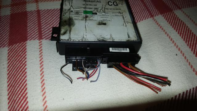
1 - Kiekert module - part number 90 564 349. Mine has alpha code CG on it.
2 - A Vectra-B key fob.
And that is it.
Just plug it in and away you go.
---------------------------------------
If you wish to add any functions,
Such as flash the indicators, or trigger the interior light....
You will also need:-
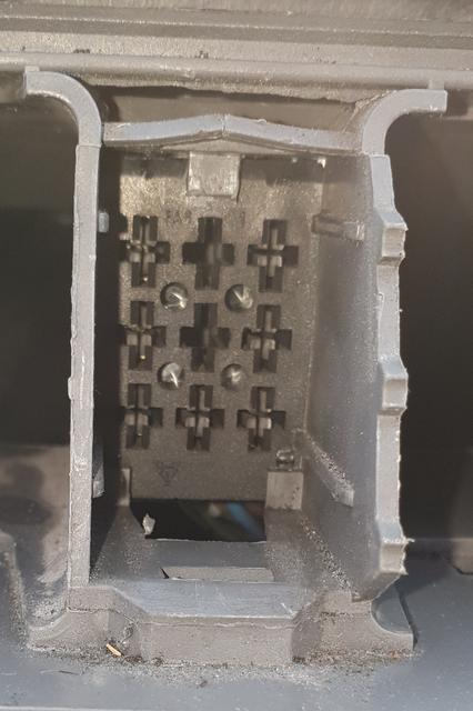
1 - the 28 pin connector,
2 - a good selection of wire,
3 - a 5 pin relay (with two 87 contacts)
Note - NOT "87 and 87A"
The relay is to drive the indicator flash, without burning out the central locking module, or overloading it's wires.
4 - a lot of crimps with rubber boots preferably .. I hate the crimps with rigid plastic covers.
Or - if you are OCD like me, solder, soldering iron and heat shrink tubing.
5 - looming tape or pvc tape to tidy up all your wires.
-----------------------------------
If you want the full alarm set-up, then it gets really complicated.
Suffice to say - You would need the Megamos unit, key fob, 28 pin connector, and also an alarm module to strip out and connect wires to.
----------------------------------
If you want comfort (full closure) wiring, then there is a separate How2 for that already.
I apologise,
I do become a bit of a nutty professor, jumping all over the place as and when I discover new information, or when I complete various tests.
----------------------------------
I shall write a formal how2 for each unit.
Give me a couple of days to put something together.
As there are so many options, depending which unit you have.
The more you want it to do, the more complex you need to make the wiring.
As for what parts you need,
------------------------------------------
For you:-
For Basic Remote Central Locking.
(Lock and unlock)
1 - Kiekert module - part number 90 564 349. Mine has alpha code CG on it.
2 - A Vectra-B key fob.
And that is it.
Just plug it in and away you go.
---------------------------------------
If you wish to add any functions,
Such as flash the indicators, or trigger the interior light....
You will also need:-
1 - the 28 pin connector,
2 - a good selection of wire,
3 - a 5 pin relay (with two 87 contacts)
Note - NOT "87 and 87A"
The relay is to drive the indicator flash, without burning out the central locking module, or overloading it's wires.
4 - a lot of crimps with rubber boots preferably .. I hate the crimps with rigid plastic covers.
Or - if you are OCD like me, solder, soldering iron and heat shrink tubing.
5 - looming tape or pvc tape to tidy up all your wires.
-----------------------------------
If you want the full alarm set-up, then it gets really complicated.
Suffice to say - You would need the Megamos unit, key fob, 28 pin connector, and also an alarm module to strip out and connect wires to.
----------------------------------
If you want comfort (full closure) wiring, then there is a separate How2 for that already.
Re: Vectra-B Remote Central Locking - Discussion
FITTING A KIEKERT VECTRA-B CENTRAL LOCKING MODULE.
THE SHORT AND TALL OF FITTING THE KIEKERT MODULE
PART NUMBER - 90 564 349
ALPHA CODE - CG.
Parts needed are: -
For Basic Remote Central Locking.
(Lock and unlock)
1 - Kiekert module - part number 90 564 349. Mine has alpha code CG on it.
2 - A Vectra-B key fob.
Ensure that the key fob is synchronised to the locking module
And that is it.
Just plug it in and away you go.
---------------------------------------
INTERIOR LIGHT ILLUMINATION FOR 2 SECONDS
The interior light illuminates for approx 2 seconds when the unlock button is pressed.
UPDATED.
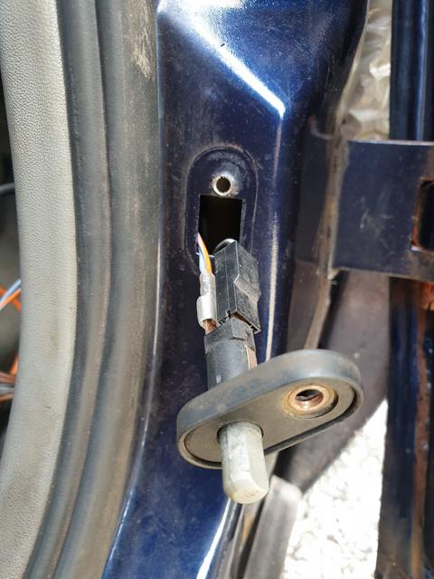
Look behind the door dip switch on the driver's door frame.
Your door dip switch has two male spade connections.
One has a single Grey / White wire to the interior light - connected via a female spade.
And multiple grey wires on the other male spade for the various door open functions.
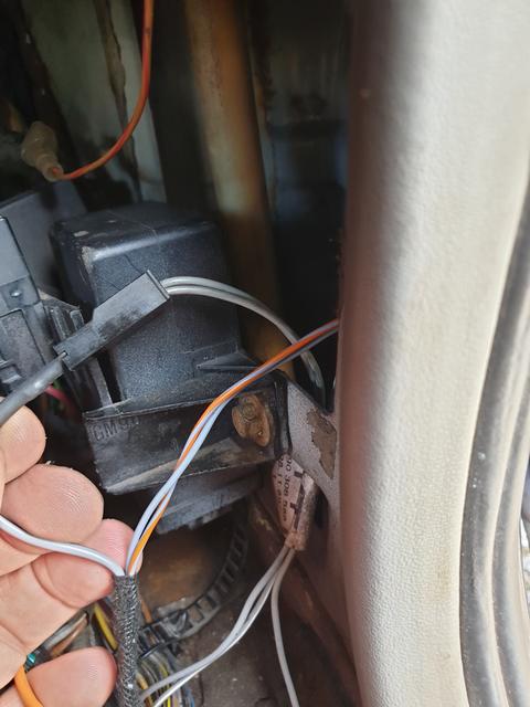
My suggestion is to daisy chain the central locking module between the door dip switch and the interior light.
1 - Fit the black / grey wire to pin 11 and fit a male spade at the end.
The wire should be long enough to reach comfortably from the module to the door dip switch.
2 - Fit a grey / white wire to pin 15 and fit a female spade connector at the end.
Again the wire should be long enough to reach comfortably from the module to the door dip switch.
3 - Unplug the grey connector already plugged into the dip switch, and connect this to the black / grey wire from pin 11.
4 - Connect the grey / white wire from pin 15 to the dip switch in place of the original grey wires.
The result is that when you unlock the doors via the fob, or after you close the door, the interior light will remain illuminated for a couple of seconds.
---------------------------------------------------------------------------------------------
FLASHING THE INDICATORS ON LOCK OR UNLOCK BUTTON PRESS.
This flashes the indicators once for about 1/2 a second on the press of a fob button.
This is best achieved using a 5 pin relay.
The relay pins are as follows:-
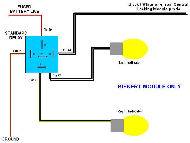
Pin 30 is battery voltage - Run to a permanent live supply. Remember to insert a fuse into this wire.
Pin 85 is the ground wire - Run a wire to a metal earthing point. You could use the hole that the self-tapping screw goes into to secure the central locking module.
Pin 86 is the control wire - This goes to Central Locking Module pin 14 of the 28 pin connector.
Pin 87 (There are two pin 87s) - Connect a wire from each of the "87" legs to each of the indicator wires.
Left is Black / White, and Right is Black / Green.
Plug in together and check your handywork.
THE SHORT AND TALL OF FITTING THE KIEKERT MODULE
PART NUMBER - 90 564 349
ALPHA CODE - CG.
Parts needed are: -
For Basic Remote Central Locking.
(Lock and unlock)
1 - Kiekert module - part number 90 564 349. Mine has alpha code CG on it.
2 - A Vectra-B key fob.
Ensure that the key fob is synchronised to the locking module
And that is it.
Just plug it in and away you go.
---------------------------------------
INTERIOR LIGHT ILLUMINATION FOR 2 SECONDS
The interior light illuminates for approx 2 seconds when the unlock button is pressed.
UPDATED.
Look behind the door dip switch on the driver's door frame.
Your door dip switch has two male spade connections.
One has a single Grey / White wire to the interior light - connected via a female spade.
And multiple grey wires on the other male spade for the various door open functions.
My suggestion is to daisy chain the central locking module between the door dip switch and the interior light.
1 - Fit the black / grey wire to pin 11 and fit a male spade at the end.
The wire should be long enough to reach comfortably from the module to the door dip switch.
2 - Fit a grey / white wire to pin 15 and fit a female spade connector at the end.
Again the wire should be long enough to reach comfortably from the module to the door dip switch.
3 - Unplug the grey connector already plugged into the dip switch, and connect this to the black / grey wire from pin 11.
4 - Connect the grey / white wire from pin 15 to the dip switch in place of the original grey wires.
The result is that when you unlock the doors via the fob, or after you close the door, the interior light will remain illuminated for a couple of seconds.
---------------------------------------------------------------------------------------------
FLASHING THE INDICATORS ON LOCK OR UNLOCK BUTTON PRESS.
This flashes the indicators once for about 1/2 a second on the press of a fob button.
This is best achieved using a 5 pin relay.
The relay pins are as follows:-
Pin 30 is battery voltage - Run to a permanent live supply. Remember to insert a fuse into this wire.
Pin 85 is the ground wire - Run a wire to a metal earthing point. You could use the hole that the self-tapping screw goes into to secure the central locking module.
Pin 86 is the control wire - This goes to Central Locking Module pin 14 of the 28 pin connector.
Pin 87 (There are two pin 87s) - Connect a wire from each of the "87" legs to each of the indicator wires.
Left is Black / White, and Right is Black / Green.
Plug in together and check your handywork.
Re: Vectra-B Remote Central Locking - Discussion
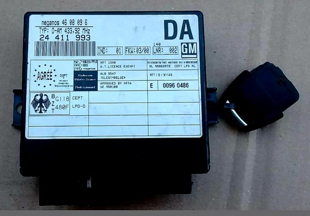
FITTING THE MEGAMOS UNIT AS A CENTRAL LOCKING MODULE.
In it's most basic function, this module requires a 12 volt supply applying to pin 18 of the 28 pin connector.
Parts required are therefore: -
1 - Megamos Central Locking Unit.
PART NUMBER is - 24 411 993
ALPHA CODE is - DA
2 - 28 Pin Connector and a length of wiring.
3 - Remote Key fob
Ensure that the key is synchronised to the module.
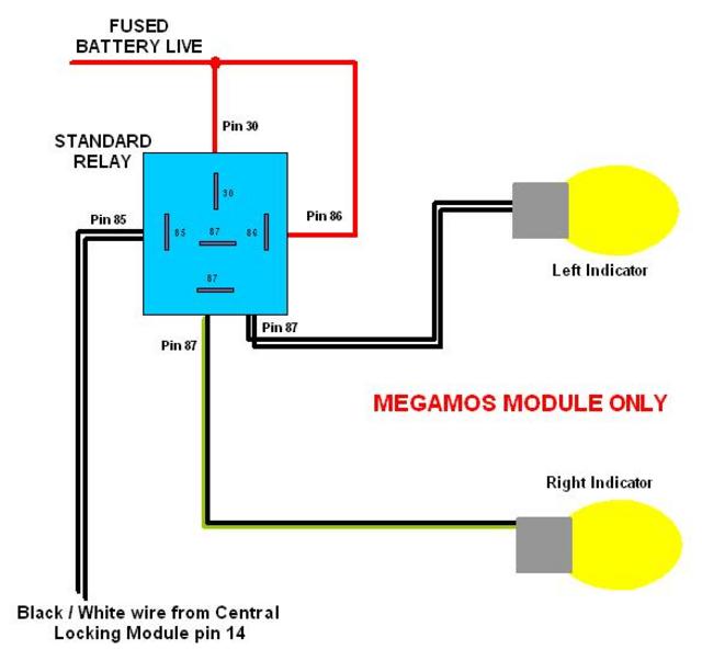
4 - To flash the indicators, you will need a relay with two 87 contacts. NOT 87 and 87a.
The "Additional Options" can be wired directly from the module connector.
Pin 10 - Dead-Lock Signal.
12 volt pulse on 2nd press of lock button, when doors are shut.
Connect to Pin 12 of the 12 pin connector.
Pin 11 - Interior Light Signal.
UPDATED.
Look behind the door dip switch on the driver's door frame.
Your door dip switch has two male spade connections.
One has a single Grey / White wire to the interior light - connected via a female spade.
And multiple grey wires on the other male spade for the various door open functions.
My suggestion is to daisy chain the central locking module between the door dip switch and the interior light.
1 - Fit the black / grey wire to pin 11 and fit a male spade at the end.
The wire should be long enough to reach comfortably from the module to the door dip switch.
2 - Fit a grey / white wire to pin 15 and fit a female spade connector at the end.
Again the wire should be long enough to reach comfortably from the module to the door dip switch.
3 - Unplug the grey / white connector already plugged into the dip switch, and connect this to the black / grey wire from pin 11.
4 - Connect the grey / white wire from pin 15 to the dip switch in place of the original grey / white wire.
The result is that when you unlock the doors via the fob, or after you close the door, the interior light will remain illuminated for about 10 to 15 seconds.
14 - Output to Flash the Indicators.
Gives a brief pulse to ground when you press the lock and / or unlock buttons.
Connect this wire to the 85 contact of a relay to trigger a flash of the indicators.
15 - Door Pin Switches.
Please see Pin 11 - Interior light triggering.
16 - Door Pin Switches.
Connect pin 16 to Grey wire in driver's door dip switch.
Prevents the setting of dead-lock with the doors open.
Used to trigger the alarm (ATWS)
Puts on interior light.
(Activates functions when wires are shorted to ground).
17 - Boot Load Area light switch. - (ATWS)
Triggers the alarm when the hatch / boot is opened. (when the wire is shorted to ground).
Connect to wire for boot light, between the bulb holder and the switch.
18 - Battery Positive supply and supply to Power sounder.
Connect to a permanent live supply via a fuse,
and also connect to positive pin on the sounder. (ATWS)
19 - Siren Return wire. (ATWS)
Ground wire for power sounder. (Connect to Sounder negative pin).
Pulses the sounder on and off.
20 - Bonnet Switch - (ATWS)
Triggers the Megamos alarm when the bonnet is opened (when the wire is shorted to ground).
Connect the wire to a dip-switch in the engine bay.
21 - Diagnostic Wire.
Allows programming / diagnostics of Megamos unit as an Anti Theft Warning System (ATWS).
The security code is needed for programming.
Connect this wire to Pin 3 of a 16 pin EOBD diagnostic connector
24 - Full Closure Wire.
If the lock button is held pressed, the electric windows and / or sunroof should close.
A Ground pulse is sent, which triggers the closure circuit. The lock button must remain pressed until the window or roof is fully closed.
Connect to pin 5 of the 12 pin connector.
In my tests this did not work, but it is meant to.
25 - Alarm Status tell-tale. (ATWS)
12 volt output to the led - Connect to 12 volt LED Anode (Positive leg)
The Cathode (negative leg) should be wired to earth.
Flashes the led quickly for 10 seconds,
then flashes once per second whilst the alarm is active.
It does not appear to indicate an alarm activation. It did on one of my tests, but I could not work out what I had done.
26 - Pane break sensor. (ATWS)
It will detect if the rear window is broken.
You wire this to the +12 terminal of the demister heater element on the rear screen.
If the glass breaks, it tears the element and cuts the link to the ground terminal of the demister element. This triggers the alarm.
Other options -
Connect to the radio ISO connector pin 1 if you have a factory radio. The alarm will trigger if the radio is removed from the car.
If none of this interests you, then simply short this wire to earth / chassis / ground.
In it's most basic function, this module requires a 12 volt supply applying to pin 18 of the 28 pin connector.
Parts required are therefore: -
1 - Megamos Central Locking Unit.
PART NUMBER is - 24 411 993
ALPHA CODE is - DA
2 - 28 Pin Connector and a length of wiring.
3 - Remote Key fob
Ensure that the key is synchronised to the module.
4 - To flash the indicators, you will need a relay with two 87 contacts. NOT 87 and 87a.
The "Additional Options" can be wired directly from the module connector.
Pin 10 - Dead-Lock Signal.
12 volt pulse on 2nd press of lock button, when doors are shut.
Connect to Pin 12 of the 12 pin connector.
Pin 11 - Interior Light Signal.
UPDATED.
Look behind the door dip switch on the driver's door frame.
Your door dip switch has two male spade connections.
One has a single Grey / White wire to the interior light - connected via a female spade.
And multiple grey wires on the other male spade for the various door open functions.
My suggestion is to daisy chain the central locking module between the door dip switch and the interior light.
1 - Fit the black / grey wire to pin 11 and fit a male spade at the end.
The wire should be long enough to reach comfortably from the module to the door dip switch.
2 - Fit a grey / white wire to pin 15 and fit a female spade connector at the end.
Again the wire should be long enough to reach comfortably from the module to the door dip switch.
3 - Unplug the grey / white connector already plugged into the dip switch, and connect this to the black / grey wire from pin 11.
4 - Connect the grey / white wire from pin 15 to the dip switch in place of the original grey / white wire.
The result is that when you unlock the doors via the fob, or after you close the door, the interior light will remain illuminated for about 10 to 15 seconds.
14 - Output to Flash the Indicators.
Gives a brief pulse to ground when you press the lock and / or unlock buttons.
Connect this wire to the 85 contact of a relay to trigger a flash of the indicators.
15 - Door Pin Switches.
Please see Pin 11 - Interior light triggering.
16 - Door Pin Switches.
Connect pin 16 to Grey wire in driver's door dip switch.
Prevents the setting of dead-lock with the doors open.
Used to trigger the alarm (ATWS)
Puts on interior light.
(Activates functions when wires are shorted to ground).
17 - Boot Load Area light switch. - (ATWS)
Triggers the alarm when the hatch / boot is opened. (when the wire is shorted to ground).
Connect to wire for boot light, between the bulb holder and the switch.
18 - Battery Positive supply and supply to Power sounder.
Connect to a permanent live supply via a fuse,
and also connect to positive pin on the sounder. (ATWS)
19 - Siren Return wire. (ATWS)
Ground wire for power sounder. (Connect to Sounder negative pin).
Pulses the sounder on and off.
20 - Bonnet Switch - (ATWS)
Triggers the Megamos alarm when the bonnet is opened (when the wire is shorted to ground).
Connect the wire to a dip-switch in the engine bay.
21 - Diagnostic Wire.
Allows programming / diagnostics of Megamos unit as an Anti Theft Warning System (ATWS).
The security code is needed for programming.
Connect this wire to Pin 3 of a 16 pin EOBD diagnostic connector
24 - Full Closure Wire.
If the lock button is held pressed, the electric windows and / or sunroof should close.
A Ground pulse is sent, which triggers the closure circuit. The lock button must remain pressed until the window or roof is fully closed.
Connect to pin 5 of the 12 pin connector.
In my tests this did not work, but it is meant to.
25 - Alarm Status tell-tale. (ATWS)
12 volt output to the led - Connect to 12 volt LED Anode (Positive leg)
The Cathode (negative leg) should be wired to earth.
Flashes the led quickly for 10 seconds,
then flashes once per second whilst the alarm is active.
It does not appear to indicate an alarm activation. It did on one of my tests, but I could not work out what I had done.
26 - Pane break sensor. (ATWS)
It will detect if the rear window is broken.
You wire this to the +12 terminal of the demister heater element on the rear screen.
If the glass breaks, it tears the element and cuts the link to the ground terminal of the demister element. This triggers the alarm.
Other options -
Connect to the radio ISO connector pin 1 if you have a factory radio. The alarm will trigger if the radio is removed from the car.
If none of this interests you, then simply short this wire to earth / chassis / ground.
Re: Vectra-B Remote Central Locking - Discussion
FITTING THE MEGAMOS AS AN ALARM MODULE.
ANTI-THEFT WARNING SYSTEM (ATWS).
ULTRASONIC WIRES.
The Pin-Out for the ultrasonics is identical between the Vectra-B wiring diagram and the Cavalier / Calibra wiring diagram.
If going for full Anti-Theft Warning System wiring, it may be best to get an old Cavalier alarm module. Strip it bare, and connect the Vectra-B 28-pin connector wires to the relevant pins of the Cavalier alarm module.
Vectra-B 28 Pin Connector - Pin-Out
Ultrasonic Sensors.
Note that the alarm will work fine without the ultrasonics.
6 - Black / Violet - Both Ultrasonic Sensors supply voltage. Cav pin 22
7 - Brown - Both Ultrasonic Sensors - ground. Cav pin 23
8 - Red / White - Left Ultrasonic Sensor Signal. Cav pin 7
9 - White - Left Ultrasonic Sensor reference. Cav pin 6
12 - Red / Blue - Right Ultrasonic Sensor Signal. Cav pin 21
13 - Blue - Right Ultrasonic Sensor reference. Cav pin 8
Dead-lock wire
10 - Black / Blue - Door Dead Locks. Cav pin 20 (?)
Full Closure
24 - Brown / Black - Roof / Window Closer. Cav pin 14 (?)
Door switches & Lighting.
14 - Black / White - Ground pulse to control a relay to flash the indicators.
15 - Grey / White - Not needed on Cav due to pin 16.
16 - Grey - Door Pin / Dip switches. Cav pin 3
17 - Brown / White - Boot / Hatch light switch. Cav pin 4
20 - Brown / Green - Bonnet Switch. Cav pin 16
26 - Black - Pane Breakage sensors.
You could use radio wire on Cav pin 9.
Or short to ground if not connected to radio.
Power Sounder
18 - Red - Battery Live and Feed to Sounder
Cav Sounder is fed direct from fused supply in the engine bay fuse box (where fitted).
THIS WIRE MUST BE CONNECTED TO A PERMANENT 12 VOLT SUPPLY IF USING THE MEGAMOS MODULE.
19 - Brown / Red - Power Sounder Return. Cav pin 24
Diagnostics
21 - Brown / White - Diagnostic Socket (3)
n/c - separate EOBD socket required.
Alarm status tell-tale
22 - Brown / White - Dash Ultrasonic disable switch.
25 - Brown / Violet - Alarm switch status LED.
Re: Vectra-B Remote Central Locking - Discussion
90 564 349 is the Vectra-B central locking module.mo_ayman wrote: What is the difference between 90-564-349 and 90-457-682? Do I need both?
90 457 682 is the Vectra-A / Cavalier mk3 / Corsa-B central locking module.
If this is a permanent fit to your car, then you do not need the Vectra-A module.
Just plug the Vectra-B module into your Vectra-A body loom.
If I add things that can be removed later, then I would use the Vectra-A casing and it's connector as an adapter plug.
This way -
if I get bored of remote locking,
or wish to revert back to normal configuration, I simply unplug the adapter loom and Vectra-B module, and refit the Vectra-A / Corsa-B module.
No mess and no hacking into car looms.
Or not as much.
THREAD UPDATE:-
I have just discovered that the Megamos unit CAN trigger the indicators to flash.
BUT - Unlike the Kiekert unit that gives a +12 volt pulse output,
The Megamos unit gives a ground pulse output.
Hence why it did not appear to work on my previous attempts.
I think that I have now fully sussed out the Megamos Central Locking module with all Anti-theft Warning System functions.
I thought it was odd to find a simpler set-up with a function above and beyond the more complex unit.
I also found a wiring issue with my adapter loom.
Although it could be something daft like I forgot to ground the comfort circuit, so it may have suffered ground back-feed.
(The circuit finds an alternative route to ground).
Either way, it would not let the interior light fade out.
Disconnected the module full-closure wire on pin 24 and the unit is working fine again.
More thoughts required.
Re: Vectra-B Remote Central Locking - Discussion
Further ponderings of an old fool, about the Megamos unit.
One thing I have not tested is the immobiliser wire.
A plan for the future maybe?
Only two tests required.
Does this wire receive a trigger pulse?
I cannot see why it would, as the unit works without the immobiliser / transponder ring fitted.
The thought is therefore - is there an output from this wire.
Is it live only when the alarm is off.?
Is it grounded only when the alarm is off.?
Whatever happens, if the alarm is to have an immobilising function, then there must be a difference taking place in the wire when the alarm is active and when it is off.
Re: Vectra-B Remote Central Locking - Discussion
Well the answer my friend is...Robsey wrote:Further ponderings of an old fool, about the Megamos unit.
One thing I have not tested is the immobiliser wire on Pin 23.
Is it live only when the alarm is off.?
Is it grounded only when the alarm is off.?
Whatever happens, if the alarm is to have an immobilising function, then there must be a difference taking place in the wire when the alarm is active and when it is off.
The wire sends a rapid flashing signal all the time, regardless of whether the ATWS is set or not.
What does change is immediately upon pressing the remote buttons - lock or unlock.
The brightness and flash-rate (frequency) increases significantly for about half of a second,
and then returns to the same brightness and frequency as before.
So nothing really useful if you do not fit the immobiliser pick up ring as well.
So the ATWS is "what it says on the tin" -it is an audible and visible warning device.
It is not an immobiliser.
For the immobiliser function you would need the transponder chip and pick-up ring... and probably the matched engine ECU as well.
Re: Vectra-B Remote Central Locking - Discussion
Referring to this topic...
Comfort Closure Circuit.
viewtopic.php?t=16669&f=15#p168886
I have now tried this circuit in conjunction with the Megamos unit.
Using the dead-lock pulse to trigger full closure.
After sorting out a few wiring mistakes, the unit now works fine on the test bench.
(Kitchen work top).
It will be interesting to see how this works in the car.
I know that accidentally leaning on the door lock plunger would trigger the full closure in the original How 2.
Using my set-up,only the dead-lock switch on the key barrel could possibly trigger this if my theory is correct.
Re: Vectra-B Remote Central Locking - Discussion
As an update, I tried the Megamos unit in the car using the adapter loom with comfort circuit.
As it happened, it worked perfectly - once.
(Just both front windows.)
After that it chose not to close the roof and windows, so I may have fried a component in the circuit board... I just don't know.
Other than that, the whole door locking module appears to work exactly as it should.
So overall - a successful experiment.
FURTHER UPDATE.
Standalone How 2's now added.
For MEGAMOS CDL and ATWS
viewtopic.php?f=70&t=16722
For KIEKERT CDL
viewtopic.php?f=70&t=16721
For COMFORT CLOSURE CIRCUIT
viewtopic.php?t=16669&f=15#p168886
Re: Vectra-B Remote Central Locking - Discussion
Just for info...
I will no longer be able to do any tests with the Kiekert remote unit.
It has now gone on a permanent summer holiday 3,600 miles away to Egypt.
Amazingly it took only 4 days to get there.
Damned expensive to post there, but hopefully the new owner will be happy with the module and matched key.
I will however be fitting the Megamos unit to my car in due course.
Plan is to wire in -
1 - The door pin switches,
2 - The power sounder (under the driver's seat).
3 - Interior light unit with delay function.
4 - Dash warning light.
5 - Indicator flashers via a relay.
Bonnet and boot switch wiring may be wired in, if I can be faffed to do so.
Coming to an update near you soon.
Re: Vectra-B Remote Central Locking - Discussion
Continuing on with the Megamos install.
Hmm - I did look at the power sounder from a 901 alarm.
Sadly it is not your standard 2 wire siren.
It has 4 wires and quite a complex circuit board on it.
I think the Vectra-B sounder is just a standard flat round horn. Not very exciting to look at.
Anyway - I have reduced my adapter loom down to just the 28 pin connector.
It is most of the way there.
Wires loomed and the tails for the door dip switches are complete.
Pins 11, 15 and 16.
The dash switch LED circuit (pin 25), will require a link to earth after the LED, which I have linked to the pain break wire on pin 26. (two birds with one stone).
The power sounder needs a location,
and a link to a fused supply, which also powers the Megamos unit.
The final job will be to link the dead-lock wire on pin 10,
And the full closure wire on pin 24,
To the 12 pin connector.
I have stripped out my full closure circuit for the final build.
Re: Vectra-B Remote Central Locking - Discussion
Pins 15 and 16 linked and extended to reach the bottom male spade of the dip-switch
And pin 11 extended to reach the female spade that was removed fron the dip-switch.
When tested it worked perfectly, putting the interior light on for 15 seconds when the doors are unlocked via the remote fob.
And pin 11 extended to reach the female spade that was removed fron the dip-switch.
When tested it worked perfectly, putting the interior light on for 15 seconds when the doors are unlocked via the remote fob.
Re: Vectra-B Remote Central Locking - Discussion
For me, the easiest / tidiest way to link up to the flashers, without going to the main alarm connector, was to daisy chain into the hazard light switch.
If you pop off the hazard switch, you will see a nine-pin socket / connector.
Two pins are not populated, but the other seven are wired up as follows -
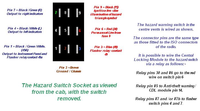
This type of connector pin is easy to extract, once you have removed the yellow plastic retainer bar.
You could use a cut-down radio ISO / SOT loom to link the three wires as required.
---------------------------------------------------
If using the Kiekert module, then you could link relay pin 85 to ground (switch pin 2)
And connect relay pin 86 to the central locking module pin 14.
(In this instance, do NOT link relay pins 30 and 86 as mentioned in the image above - that is for Megamos only).
Remembering that: -
The Kiekert module is +12 volt triggered.
The Megamos module is ground triggered.
Referring to the image above, the numbers in brackets are the identifiers used in the Haynes Manual schematic diagrams.
Oddly none of the numbers in the Haynes manual match up to my sketch above, but
The pins 1 to 9 in the sketch refer to the pin identifications on the switch itself..

Yes, I know the numbers are upside down, but that is the orientation of the switch in the dash. That is just another quirk from them crazy folk at Vauxhall / Opel / GM.
Late Night Update -
I have now made up the loom to link into the hazard switch from the relay and the central locking module.
If you pop off the hazard switch, you will see a nine-pin socket / connector.
Two pins are not populated, but the other seven are wired up as follows -
This type of connector pin is easy to extract, once you have removed the yellow plastic retainer bar.
You could use a cut-down radio ISO / SOT loom to link the three wires as required.
---------------------------------------------------
If using the Kiekert module, then you could link relay pin 85 to ground (switch pin 2)
And connect relay pin 86 to the central locking module pin 14.
(In this instance, do NOT link relay pins 30 and 86 as mentioned in the image above - that is for Megamos only).
Remembering that: -
The Kiekert module is +12 volt triggered.
The Megamos module is ground triggered.
Referring to the image above, the numbers in brackets are the identifiers used in the Haynes Manual schematic diagrams.
Oddly none of the numbers in the Haynes manual match up to my sketch above, but
The pins 1 to 9 in the sketch refer to the pin identifications on the switch itself..
Yes, I know the numbers are upside down, but that is the orientation of the switch in the dash. That is just another quirk from them crazy folk at Vauxhall / Opel / GM.
Late Night Update -
I have now made up the loom to link into the hazard switch from the relay and the central locking module.
Re: Vectra-B Remote Central Locking - Discussion
Righty-oh...
I have now made up all the different parts of the loom.
Hopefully have time this afternoon to test the whole thing, including: -
The power sounder,
The dip-switch connections,
The secondary battery live link,
The dash switch led wiring and ascociated ground wire,
The five pin relay and hazard lights wires...
It should virtually mimic a late Vectra-B remote central locking and anti-theft warning system.
I will put up pictures or a few gifs later
Re: Vectra-B Remote Central Locking - Discussion
Okay neither the relay nor sounder worked.
The ground trigger did not seem to work from pin 14.
But the hazards flashed when the relay pin 85 was shorted to earth.
Maybe I need to re-check the output from pin 14 again.
And I think the sounder needs to be a proper horn, not a normal alarm siren.
I should have a horn in my box of spares.
The ground trigger did not seem to work from pin 14.
But the hazards flashed when the relay pin 85 was shorted to earth.
Maybe I need to re-check the output from pin 14 again.
And I think the sounder needs to be a proper horn, not a normal alarm siren.
I should have a horn in my box of spares.
Re: Vectra-B Remote Central Locking - Discussion
Updates on the output to indicator flash relay.
It would appear that the pulse out from pin 14 is not sufficient to operate the relay.
It is indeed a "low level" pulse, but not direct to ground.
Low enough to flash an LED, but not enough to trigger a relay.
Hmmm.
And I haven't tested the theory, but I am 99.9% certain, that a normal flying saucer style horn is required fot the audible alarm.
I presume the "901" sounder is actually a glorified speaker, not a horn, hence the complex circuit board that it is plugged into.
Re: Vectra-B Remote Central Locking - Discussion
I have now added -
How the Megamos unit controls the interior light.
See the Megamos How 2 in the link a few posts above.
--------------------------------------------
Still plenty of head scratching to do.
Intermittent Key Fob Signal.
Since fitting the module to my car, I am struggling with the lock / unlock signal getting from the fob to the module.
Maybe it is the abs panel that I made to mount it. It could be too wide, blocking the signal, so it may need trimming down a bit.
The battery could be getting low / discharged, although this has only happened since fitting it to the car.
Or it could be the fob itself...
I swapped the casing at the same time as fitting the module to the car.
As with many of these Vectra-B key fobs, mine had a wad of folded paper inserted between the battery and casing, to ensure a good contact.
Maybe the wadding has not been fitted quite correctly, causing an intermittent signal.
-----------------------------------------
Indicator Flash on Lock and Unlock Signal.
I have a different relay that will trigger from as little as 3volts,
I could try this to see if it is able to flash the indicators, albeit by another relay with twin 87 contacts....
Watch this space?
Re: Vectra-B Remote Central Locking - Discussion
I refitted the wadding and cellotaped it in place. The red led seems to work better, indicating that battery connection is no longer intermittent.Robsey wrote: Intermittent Key Fob Signal.
As with many of these Vectra-B key fobs, mine had a wad of folded paper inserted between the battery and casing, to ensure a good contact.
Maybe the wadding has not been fitted quite correctly, causing an intermittent signal
I will check it against the car tomorrow.
If this now works, I will solder a fine wire from the battery holder terminal to it's solder-pad on the circuit board. - some time over the weekend.
Re: Vectra-B Remote Central Locking - Discussion
The outcome is "some" improvement in reliability of operating the central locking via the fob.
Maybe it will need a bit of trimming of the mounting strip, and a bit of re-routing of the wiring to reduce electrical 'noise' in that area.
I still have not completely worked out all the weird reasons why the central locking module sometimes turns the alarm led on when I lock the doors via the key, and sometimes not.
And sometimes the module turns the alarm led off when I unlock the doors by the key, and sometimes when I turn on the ignition.
But none of them in a consistent manner.
The only consistent thing is the module always turns the alarm led on, when I turn the driver's door lock from dead-lock to normal lock position.
Turning to the unlock position still shows the alarm led as being on.
Clarity will probably only be achieved, when I have all four doors locking and unlocking in unison as they should.
At which stage, I will probably rip out the megamos, refit the original central locking module, and then connect the lock, unlock and dead-lock wires to my Scorpion alarm instead.
UPDATE :-
Fob reliability issues now sorted.
A quick solder job and a new battery for the win.
See here
viewtopic.php?f=15&t=16753&p=169606
Another UPDATE - 24_10_2019.
I finally got the HU43 horseshoe key cut for the car.
Local lock-smiths / key supplier cut the key blade to the code on the car pass.
All works fine, although the driver's door and rear hatch lock barrels were initially a little stiff. Ignition barrel was fine.
All good now though.
Happy days.
Re: Vectra-B Remote Central Locking - Discussion
Did you ever suss out the indicator flash of the relay? Just fitted a bosch unit to mine, locks/unlocks perfectly but want to wire it for the indicator flash
Re: Vectra-B Remote Central Locking - Discussion
I did not get that far...
Although I do plan to finish the wiring in May.
All I need to do, is find out the polarity and magnitude of the output pulse from the indicator flash pin.
I will have to put a volt-meter between the trigger pin and ground,
To prove positive voltage trigger,
Or
Between the trigger pin wire and a 12 volt supply,
To prove that it is a ground trigger.
Re: Vectra-B Remote Central Locking - Discussion
Another consideration, is that I was bogging about trying to connect to the indicators via the hazard switch.
A sensible person would have connected to the long yellow alarm connector behind the glove box.
I didn't, because I have a separate Scorpion alarm wired to that.
So, it maybe that I got confused on the hazard switch connections.
Easily done when spending ten minutes here and ten minutes there during your lunch breaks.
Just to add-
The indicator wires in the alarm module connector are -
Pin 12 = Black / white wire for left indicators.
Pin 25 = Black / green for right indicators.
Re: Re: Vectra-B Remote Central Locking - Discussion
You have collected a lot of information on locks, which will help owners solve problems that often arise.
Re: Re: Vectra-B Remote Central Locking - Discussion
Was there a win in decoding damps from 93cl46?