
Yes - full closure, hold the lock button on the key pressed.
Just like you hold the key in the lock barrel in the lock position (45° angle) to close the windows.(facelift cars only).
Deadlock is a bit faffy, where you need to fit a passenger side lock motor to the driver's door.
So you would lose the mechanical (lock barrel) dead lock facility.
But a double press of the lock button on the key does this for you.
One other function you lose is the unlocking and locking of the car from the hatch / boot lock barrel.
On the Vectra-b and Omega-b module, there is no signal "from" the switches on the hatch / boot lock barrel.
So - turning the key to unlock the boot / hatch lock barrel will not operate the door locks.
But the door locks will operate the hatch / boot lock.
Re: Vectra-B Remote Central Locking - Discussion
Moderator: Robsey
-
vectra1903

- Registered user
- Posts: 167
- Joined: Fri Sep 27, 2019 8:44 pm
- Location: Poland
Re: Re: Vectra-B Remote Central Locking - Discussion
I have a Kiekert remote central locking ECU. What would I need to make it blink the hazards and maybe sound the horn when locking/unlocking? Would I need to route any wires out of the interior or is this avoidable?
Re: Re: Vectra-B Remote Central Locking - Discussion
The Kiekert unit is discussed here..
viewtopic.php?f=70&t=16721
Sounding the horn... I think you need the Megamos version for that.
BUT - you could use the hazard flashing wire on pin 14 to trigger a relay to operate the horn.
Are you sure you want to sound the horn every time you lock and unlock the doors.?
It may be better to use a 12 volt buzzer instead.
Less of a hassle if you operate the locks during the night.
But flashing the hazards should be doable, using the long yellow relay as used in the omega-b.
Discussed here in the Megamos thread
viewtopic.php?f=70&t=16722
Extra Comment -
For some items to work, you need to link to the yellow alarm connector bdhind the glovebox.
This is true for the indicator outputs from the yellow relay.
And I believe for the dead-lock (second fob press) black/blue wire.
The alarm connector is here.
viewtopic.php?f=70&t=17144
Re: Re: Vectra-B Remote Central Locking - Discussion
I have looked at the wiring diagram for the Cavalier / Vectra A alarm and the horn relay (for dual horn / fanfare vehicles).
It appears that the brown / red wire (pin 24) in the yellow alarm connector is already connected to the "85" terminal of the horn relay.
Therefore - if you can put a temporary ground wire on the alarm connector, it should sound the horn.
If that is the case, you could then use a relay to operate the horn(s).
Re: Re: Vectra-B Remote Central Locking - Discussion
Indicator flasher wire...
14 - Output to Flash the Indicators.
Gives a brief pulse to ground when you press the lock and / or unlock buttons.
(Taken from megamos thread - so check output of black/white wire - and link the appropriate polarity to suit).
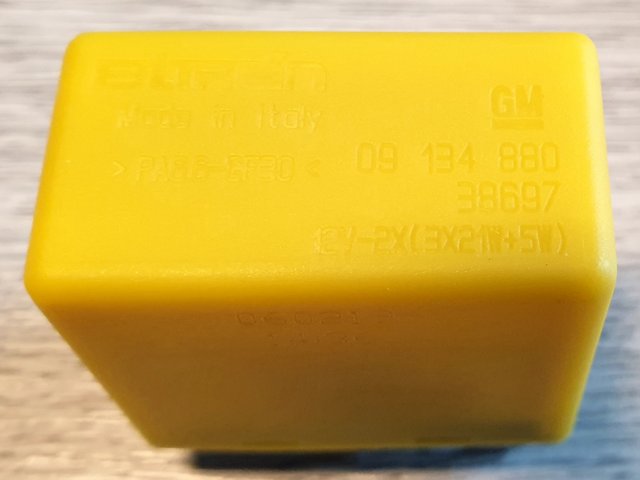
For flashing the indicators when arming and disarming the anti-theft module I have discovered that the Vectra-B uses a specific yellow relay.
Part number 9134880.
Approx £18 from GPS for GM part, or £21 for an OEM part.

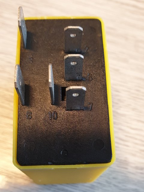
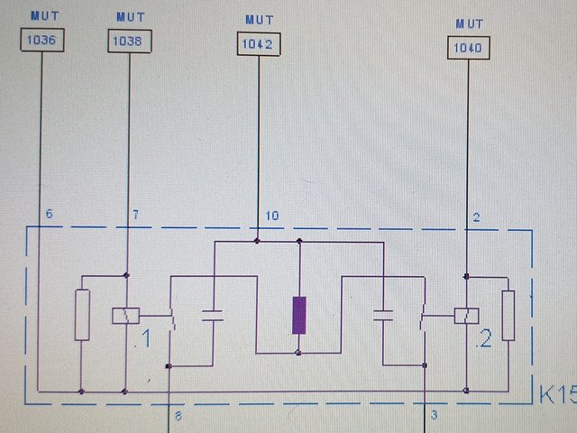
I have looked into how it "should" work.
All three red feed wires should be connected to battery live. (Relay pins 2, 7 and 10).
This relay is independent of the indicator and hazard flasher unit on the Cavalier.
You can connect them all to cavalier alarm connector pin 13 - red wire. *** check polarity of anti-theft pin 14 first
Pin 6
black / white wire to the anti-theft connector pin 14 (28 pin plug). *** check polarity first.
Flash control trigger wire.
Pins 3 and 8 are outputs to the indicators.
Pin 3
black / green (right) to cavalier alarm plug pin 25,
Pin 8
black / white (left) to cavalier alarm plug pin 12.
--------------------------------------------------------
14 - Output to Flash the Indicators.
Gives a brief pulse to ground when you press the lock and / or unlock buttons.
(Taken from megamos thread - so check output of black/white wire - and link the appropriate polarity to suit).
For flashing the indicators when arming and disarming the anti-theft module I have discovered that the Vectra-B uses a specific yellow relay.
Part number 9134880.
Approx £18 from GPS for GM part, or £21 for an OEM part.
I have looked into how it "should" work.
All three red feed wires should be connected to battery live. (Relay pins 2, 7 and 10).
This relay is independent of the indicator and hazard flasher unit on the Cavalier.
You can connect them all to cavalier alarm connector pin 13 - red wire. *** check polarity of anti-theft pin 14 first
Pin 6
black / white wire to the anti-theft connector pin 14 (28 pin plug). *** check polarity first.
Flash control trigger wire.
Pins 3 and 8 are outputs to the indicators.
Pin 3
black / green (right) to cavalier alarm plug pin 25,
Pin 8
black / white (left) to cavalier alarm plug pin 12.
--------------------------------------------------------
Re: Re: Vectra-B Remote Central Locking - Discussion
If the Kiekert is positive switching,
Then Kiekert pin 14 to relay pins 2 and 7.
Relay pin 6 to ground.
Relay pin 10 to the fat red in the Cavalier alarm connector. (Pin 13)
Pins 3 and 8 of the relay remain unchanged - output wires to the Cavalier alarm connector pins 12 and 15.
Then Kiekert pin 14 to relay pins 2 and 7.
Relay pin 6 to ground.
Relay pin 10 to the fat red in the Cavalier alarm connector. (Pin 13)
Pins 3 and 8 of the relay remain unchanged - output wires to the Cavalier alarm connector pins 12 and 15.
Re: Re: Vectra-B Remote Central Locking - Discussion
Horn trigger...again another relay.
Plenty of room on the shelf at the back of the glove box, behind the dash.
Also assuming that the flying lead on Cavalier alarm plug pin 24 sounds the horn when the other end is touched to earth.
Dependent upon Kiekert pin 14 polarity.
For positive output.
If Kiekert 14 is positive (12v) then connect this to relay pin 86
Connect relay pin 85 to ground.
Connect relay pin 30 to ground (moderate wire).
Connect relay pin 87 to Cavalier alarm connector pin 24.
--------------------------
For positive output.
If Kiekert 14 is negative (0v) then connect to relay pin 85
Connect relay pin 86 to the red battery live of the Cavalier alarm connector. (Pin 13)
Connect relay pin 30 to ground (moderate wire).
Connect relay pin 87 to Cavalier alarm connector pin 24.
Re: Re: Vectra-B Remote Central Locking - Discussion
Hmm - Okay, I think I need to revisit this thread, to finish my Megamos install.
At the moment, the car has been stood for 2 1/2 years without a battery. Well it had a battery for the first six months, but with the Megamos and the Scorpion alarm both wired in and powered up, it became a matter of recharging the battery every couple of weeks until the battery died altogether.
-----------------------------
Roll the clock forward to the here and now.
To keep the Cavalier knowledge active in my head, I thought it would be good to do some "Winter" projects.
And what better than an adapter loom to link the Megamos anti-theft warning system module to the Cavalier anti-theft / alarm unit connector.
The theory has been hammered to death, and I do apologise for that.
As you probably know, my Scorpion is currently attached to the car via a butchered Cavalier alarm module - case and connector with all the components stripped out.
I plan to do the same again for the megamos.
Therefore -
First job is to find a knackered alarm unit that I can gut and modify.
Then I will make up the necessary link looms.
Parts to link are:-
Megamos in drivers footwell / kick panel.
Cavalier alarm that is stashed in the left wing next to the glovebox on UK cars.
And on the back of the glovebox will be the yellow indicator relay.
...
...
And possibly an internally mounted power sounder to scare the S#!7 out of any would-be thieves.
On the down-side, the Megamos does not have an immobiliser function... that would be dealt with via the immobiliser pick-up and the engine ECU.
It should be straight forward.
Let's hope practice matches theory.
Sod's law means that something is bound to go pear shaped.
Re: Re: Vectra-B Remote Central Locking - Discussion
I am scratching my head with the Cavalier connections for the central locking.
Alarm Pin 11 - Black / Red - Boot lock motor (M37) pin 3
Central Locking module pin 6.
Alarm Pin 15 - Brown / White - Boot lock motor (M37) pin 2
Central Locking module pin 4.
Calibra boot lock switch. (Normally open) shorted to ground when switch 'closed'.
Alarm Pin 20 - Black / Blue - Drivers Door barrel switch common contact.
Central Locking module pin 12 does not work.

Re: Re: Vectra-B Remote Central Locking - Discussion
That seems right, though it would mean you can only unloick from the boot and not lock for the central locking.
Pin12 is the driver's key feed, what do you mean by not working?
Why do you need the alarm inputs? I'm guessing they are all just signals to say the car is locked or unlocked, so alarm off or on.
Pin12 is the driver's key feed, what do you mean by not working?
Why do you need the alarm inputs? I'm guessing they are all just signals to say the car is locked or unlocked, so alarm off or on.
David
Re: Re: Vectra-B Remote Central Locking - Discussion
As such - I do not need them - the remote lock and unlock works already.
But if a job is worth doing, it should be done properly.
After checking all my Excel spreadsheets, I think a "maxed-out" link would require 9 wires from the ATWS unit 28-pin plug.
Pin 1 - black / red to Cavalier plug pin 14
Door Unlock Signal.
Pin 2 - Brown / white to Cavalier plug pin 11
Door Lock Signal
Pin 10 - black / blue to Cavalier plug pin 20
Door Dead Lock Signal
Pin 14 - black / white to Indicator Flasher Relay pin 6
Pin 18 - Red - to Cavalier plug pin 13
Fused Supply from Fuse 30 (10 amp).
And to Power Sounder "+"
Pin 19 - Brown / Red - to Cavalier plug pin 24
Power Sounder return. ("-")
Pin 20 - Brown / Green - to Cavalier plug pin 16.
Bonnet Contact switch.
Pin 24 - Brown / Black - to Cavalier plug pin 15
Pin 26 - Black - to Cavalier plug pin 4.
Rear window pane break wire.
------------------
Additionally for the Indicators.
Flasher Relay Pin 2 - red - to Cavalier plug pin 13
Battery Live from Fuse 30.
Flasher Relay Pin 3 - Black / Green - to Cavalier plug pin 25.
Right Turn Signal
Flasher Relay Pin 7 - red - to Cavalier plug pin 13
Battery Live from Fuse 30.
Flasher Relay Pin 8 - Black / White- to Cavalier plug pin 12
Left Turn Signal
Flasher Relay Pin 10 - red - to Cavalier plug pin 13
Battery Live from Fuse 30.
Re: Re: Vectra-B Remote Central Locking - Discussion
But as said - we can omit the door lock links.
ATWS - pin 1 to Cav pin 14
ATWS - pin 2 to Cav pin 11
Giving a simple 7 wire loom.
ATWS - pin 1 to Cav pin 14
ATWS - pin 2 to Cav pin 11
Giving a simple 7 wire loom.
Re: Re: Vectra-B Remote Central Locking - Discussion
What I mean is - initial logic would suggest the following connections.
ATWS 28-Pin Plug - Pin 10 to Cavalier 12 pin central locking plug pin 12.
But this does not operate the dead lock feature.
What you would have to do is link -
ATWS 28-Pin Plug - Pin 10 to Cavalier 25 pin Alarm plug pin 20.
It will then work.
Same issue with Full Closure.
ATWS 28-Pin Plug - Pin 24 to Cavalier 25 pin Alarm plug pin 15.... Not to Cavalier 12-pin central locking module pin 5.
------------------------
On the Vectra-B set-up, the dead-lock micro-switch is not used.
To replicate this in the Cavalier, we need to fit a passenger door lock solenoid to the driver's door.
And then dismount the micro-switches from the barrel, but leave them electrically connected, tucked out of the way.
Re: Re: Vectra-B Remote Central Locking - Discussion
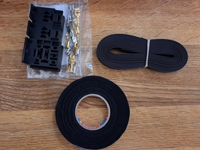
I have ordered some inter-locking relay bases with crimp-on connectors.
Of course, mine will be crimped and soldered... and sleeved.
This comprises:-
2 x micro relay bases, as these are both required for the yellow indicator relay.
1 x standard relay base for the fuel pump immobiliser relay.
Approx £7 including postage.
And also a used 25-pin alarm module is on it's way.
Approx £21 including postage.
I will make up a relay base mounting panel from salvage polyprop sheet at work, which I will Velcro onto the shelf at the back of the glovebox, per standard Vauxhall methodology.
And wires from my huge array of spare VW wiring looms.
Thankfully VW and Opel both use the same wiring colour schemes for many items.
This should satisfy my o.c.d. for keeping everything "in alignment" with the original manufacturers' looms etc.
I should be able to complete the whole job for under £30.

I am trying not to 'blow the budget', so keeping costs to a minimum, but still trying to do things properly.
Just like many members - trying to work on multiple vehicles can get very expensive and draining on time, energy and resources.
The Cav hasn't seen much love for over a year, so time to endulge again.
As usual, I will report my findings - both good and bad.
Oh yes... I need to "borrow" a used powered wheelchair battery - for test purposes of course.
Hmm - I also need some more looming tape.
I don't think I have much left from all the VW projects.
UPDATE - Tubing and tape now ordered.
Of course, mine will be crimped and soldered... and sleeved.
This comprises:-
2 x micro relay bases, as these are both required for the yellow indicator relay.
1 x standard relay base for the fuel pump immobiliser relay.
Approx £7 including postage.
And also a used 25-pin alarm module is on it's way.
Approx £21 including postage.
I will make up a relay base mounting panel from salvage polyprop sheet at work, which I will Velcro onto the shelf at the back of the glovebox, per standard Vauxhall methodology.
And wires from my huge array of spare VW wiring looms.
Thankfully VW and Opel both use the same wiring colour schemes for many items.
This should satisfy my o.c.d. for keeping everything "in alignment" with the original manufacturers' looms etc.
I should be able to complete the whole job for under £30.
I am trying not to 'blow the budget', so keeping costs to a minimum, but still trying to do things properly.
Just like many members - trying to work on multiple vehicles can get very expensive and draining on time, energy and resources.
The Cav hasn't seen much love for over a year, so time to endulge again.
As usual, I will report my findings - both good and bad.
Oh yes... I need to "borrow" a used powered wheelchair battery - for test purposes of course.
Hmm - I also need some more looming tape.
I don't think I have much left from all the VW projects.
UPDATE - Tubing and tape now ordered.
Re: Re: Vectra-B Remote Central Locking - Discussion
Here is the planned adapter loom
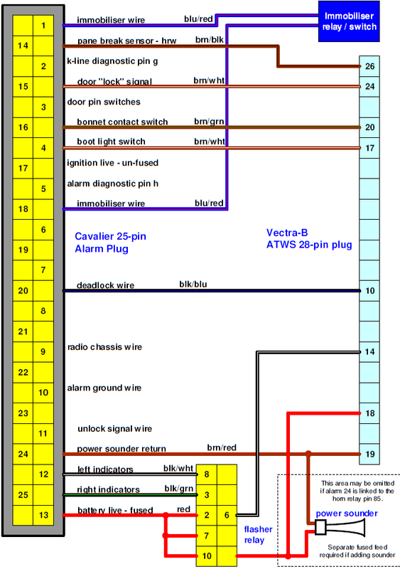
UPDATE - Pin assignment now corrected.
UPDATE - Pin assignment now corrected.
Re: Re: Vectra-B Remote Central Locking - Discussion
That pin 12 is more complex than it looks, I'm guessing S41 is the deadlock switch. It looks like it forces the motors to lock is changed over, The normal position of that switch is to ground one side of the motors, and activating the switch connects pin 12 through to one side of all motors. The operation depends on the internal switch positions on the door locks, and it's not clear what position they are in for locked or unlocked.
David
Re: Re: Vectra-B Remote Central Locking - Discussion
Looking at the Cavalier Deadlock Micro-switches.
"Normal Locked and Unlocked Position" -
Normally Closed (NC) is -
Black/blue wire is shorted to ground.
Normally Open (NO) is -
Yellow / Red wire is open circuit.
Dead Locked position -
Yellow / Red wire is shorted to black / blue.
And.
Ground goes open circuit.
As viewed in Haynes' over simplified schematic diagram.
When the deadlock wire is shorted to yellow/red it disconnects the ground link from all "slave" lock motor circuits
That is front passenger and both rear door locks.
And so as such - kills the door lock electrics - dead!
Re: Re: Vectra-B Remote Central Locking - Discussion
The system as it stands can put 0v or 12v to either side, so motor goes back or forward depending on if it is 12v-and-0v or 0v-and-12v on the motor connections.
For the slave motors (passenger + back), they have the change over switchbuilt in, it's not clear if it's shown as locked or unlocked, say for pins 6 and 2 of M32 for connections.
The S42 is the passenger lock switch, if we say it's all shown as unlocked, it's tied to the drivers lock switch in an odd way, and that doesn't seem right as the normal position shown in the haynes as it means the passenger door lock switch wont work as M18 has it grounded.
David
Re: Re: Vectra-B Remote Central Locking - Discussion
Hmmm -
after a lot of to-ing and fro-ing between various pin outs, schematics and TIS documents...
I 'think' that I have come to the conclusion that pins 1 and 2 in the 28-pin plug merely duplicate the functions of pins 2 and 6 in the 12-pin plug.
More or less the inputs from the passenger door locking motor electrics.
Which is odd as pins 2 and 6 are present in the 12-pin plug on the Vectra-B and later Omega-B.
Full closure should be a fore-gone conclusion, as it should work on prolonged pressing of the fob lock button. Cavalier CDL pin 5 is not populated on the Megamos and Vectra-B Kiekert, hence why closure does not work via the fob unless wired to the Cavalier alarm plug.
That leaves the deadlock wire on pin 10.
As discussed, we know this should work anyway if connected to the Cavalier alarm plug.
We assume that pin 12 of the Cavalier CDL plug is not populated in the Megamos and Vectra-B Kiekert units.
Re: Re: Vectra-B Remote Central Locking - Discussion
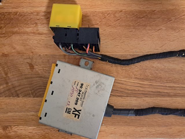
Oh dear - parts have arrived for the conversion loom.
Looks like I have a job to do this weekend.
A bit deja-vue
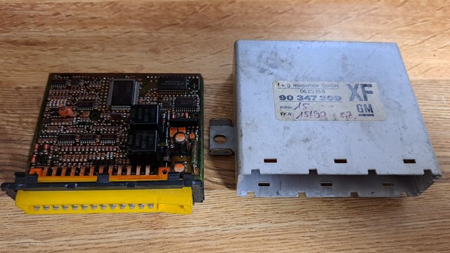
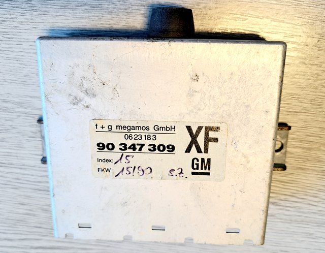
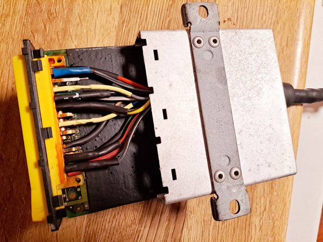
Looking at the inside of the Cavalier / Calibra / 1990's Omega-B anti-theft module.
Crammed full of SMD components.
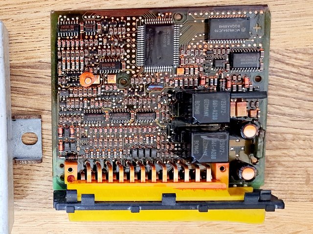
Until I strip it bare of course, ready for soldering on the new wires...
Sounds a shame to strip a perfectly good working module, but there is no other way to do this adapter tidily.
Should be somewhere between 7 and 10 wires, depending on how things go with confirming the lock and unlock pin - outs.
Just to take the pee....
I have mis-placed the yellow relay - grrrrr!!
Update:- turned the house, shed and kennel upside-down.
I still cannot find the chuffin' relay.
Looks like I have a job to do this weekend.
A bit deja-vue
Looking at the inside of the Cavalier / Calibra / 1990's Omega-B anti-theft module.
Crammed full of SMD components.
Until I strip it bare of course, ready for soldering on the new wires...
Sounds a shame to strip a perfectly good working module, but there is no other way to do this adapter tidily.
Should be somewhere between 7 and 10 wires, depending on how things go with confirming the lock and unlock pin - outs.
Just to take the pee....
I have mis-placed the yellow relay - grrrrr!!
Update:- turned the house, shed and kennel upside-down.
I still cannot find the chuffin' relay.
Re: Re: Vectra-B Remote Central Locking - Discussion
Board completely stripped bare.
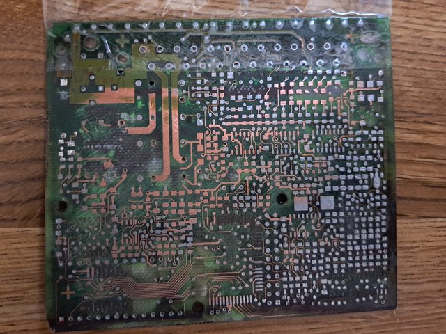
Yellow connector stripped - legs that I will be connecting to have been straightened so that wires pass horizontally into casing.
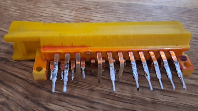
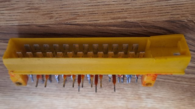
Unused legs will be soldered back onto the bare pcb for secure mounting purposes.
Next task is to measure distance from the alarm location to the glovebox shelf.
Then glovebox shelf to the anti-theft central locking module in the driver's footwell.
Noting that the cable routing is -
From the left wing to the glovebox shelf
From the shelf to the top right corner of the glovebox aperture
Into the top left corner of the dash next to the clock / board computer.
Down the left side towards the cigarette lighter,
Across to the otherside of the ash-tray,
And up the right side of the radio and heater panel towards the dash.
Across to the right end of the dash, past the fusebox, towards the yellow 4x4 connector.
And down to the floor behind the kick panel.
Yellow connector stripped - legs that I will be connecting to have been straightened so that wires pass horizontally into casing.
Unused legs will be soldered back onto the bare pcb for secure mounting purposes.
Next task is to measure distance from the alarm location to the glovebox shelf.
Then glovebox shelf to the anti-theft central locking module in the driver's footwell.
Noting that the cable routing is -
From the left wing to the glovebox shelf
From the shelf to the top right corner of the glovebox aperture
Into the top left corner of the dash next to the clock / board computer.
Down the left side towards the cigarette lighter,
Across to the otherside of the ash-tray,
And up the right side of the radio and heater panel towards the dash.
Across to the right end of the dash, past the fusebox, towards the yellow 4x4 connector.
And down to the floor behind the kick panel.
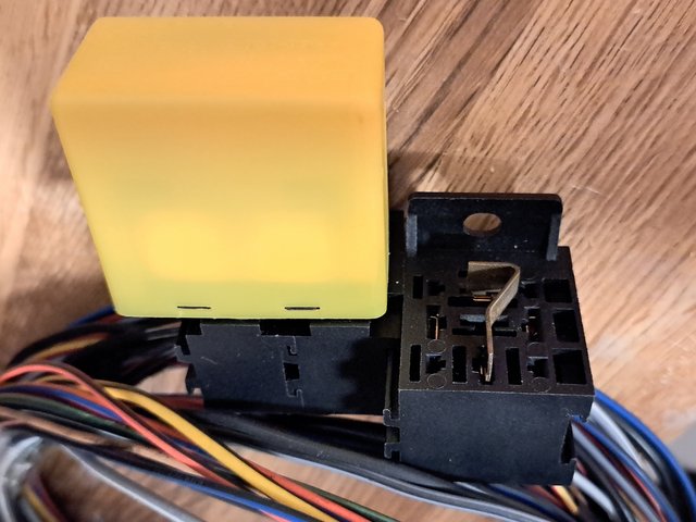
Re: Re: Vectra-B Remote Central Locking - Discussion
The original wires and female spades fitted to the relay did not have retaining tangs,
so they were all cut off.
New female spades were crimped and soldered in place, and clipped into the double-gang bases.
Thankfully, the relay does fit two micro-relay bases slotted together. A very secure fit.
Just the immobiliser relay to wire up now.
Possibly to a dash switch - always good to have a security switch in plain view.
Re: Re: Vectra-B Remote Central Locking - Discussion
Oh blimey.... the cable is getting quite substantial.
Like a complete car loom of it's own.
I have left off the lock and unlock wires as they are probably not needed.
I have wired in the immobiliser relay.
The immobiliser (pins 1 and 18) loop and the relay ground all go to the alarm for tidiness.
Only the on / off (switched live) trigger wire will go a different way - towards a spare dash switch.
I also found a nifty relay bypass jobbie from an old VW CE1 fusebox.
I could keep it in my "emergency kit" incase the immobiliser relay packs up.
My O.C.D. in my head is telling me that I have a yellow 40 amp relay in my Vectra spares relays box.
Hmmm all yellow electrics... probably a step too far.
Next job is to drill the alarm casing so that the wires can pass through.
Until that is done, I cannot solder the wires from the relays to the alarm connector.
Then it will be a matter of making up connections for the megamos unit.
Re: Re: Vectra-B Remote Central Locking - Discussion
So what do we have?
Alarm 1 - blue/red to immobiliser relay pin 30.(supply)
Alarm 10 - brown to immobiliser relay pin 85 (ground)
Alarm 18 - blue/red to immobiliser relay pin 87.(load)
Alarm 4 - brown/white to Megamos 17 (boot contact)
Alarm 14 - brown/black to Megamos 26 (pane break)
Alarm 16 - brown/green to Megamos 20 (bonnet contact)
Alarm 12 - black/white to flasher relay pin 8 (left turn)
Alarm 13 - red to flasher relay pins 2, 7, and 10 plus Megamos pin 18 (unfused 12 volts).
Alarm 25 - black/green to flasher relay pin 3 (right turn)
Alarm 17 - black to be decided - unfused ignition live.
Alarm 20 - black/blue to Megamos pin 10 (deadlock).
Alarm 24 - brown/red to Megamos pin 19 (horn control)
This leaves -
Flasher relay pin 6 - black/white to Megamos pin 14 (flasher relay ground trigger).
Immobiliser relay pin 86 - yellow/red to switched live on a dash switch (immobiliser kill switch).
Re: Re: Vectra-B Remote Central Locking - Discussion
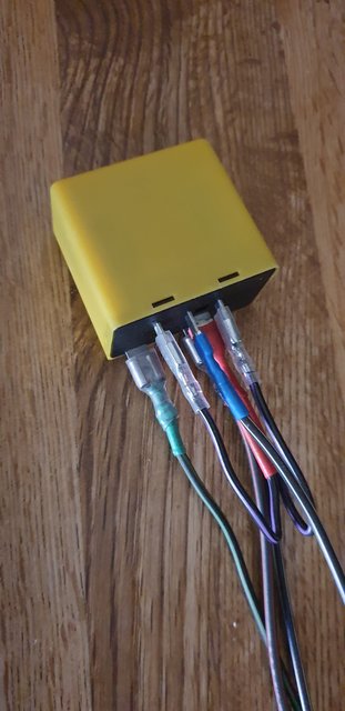
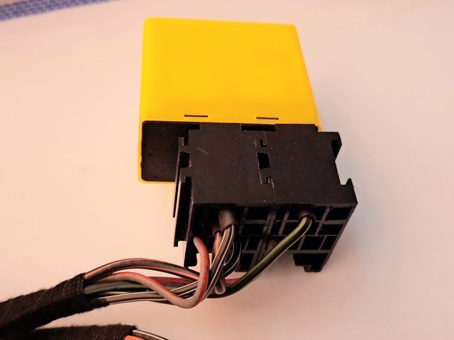
Casing drilled and relinquished grommet fitted.
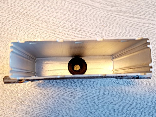
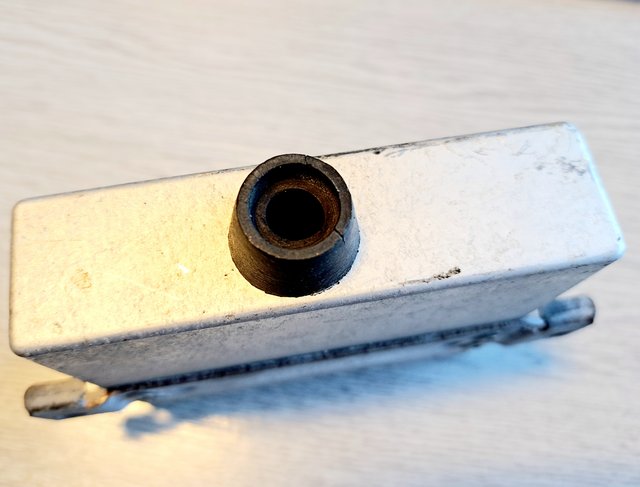
The wires 'just' fit through the bore.
UPDATE - 19_10_2022
The Cavalier alarm plug and relays are all soldered, sleeved, and loomed up.
I just need to get some dimesions for draping the loom across towards the driver's footwell (Megamos ATWS).
The wires 'just' fit through the bore.
UPDATE - 19_10_2022
The Cavalier alarm plug and relays are all soldered, sleeved, and loomed up.
I just need to get some dimesions for draping the loom across towards the driver's footwell (Megamos ATWS).