Fitting Cruise Control to a Cav Mk3 - The electrics.

An index of useful guides designed to help you care for and maintain your Mk3 Cavalier

Moderator: Robsey

Locked
User avatar
Robsey
Club Admin
Posts: 10596
Joined: Fri Dec 12, 2008 1:42 pm
Location: East Manchester

Fitting Cruise Control to a Cav Mk3 - The electrics.

Post by Robsey »

I am writing this thread, as it is my plan to fit cruise control to my 4 Pot Cavalier (C20NE).
There are many other How 2's around covering this project / adaptation / Upgrade.

This one can be discussed here: -

viewtopic.php?f=15&t=16368

There is one on here that Squig wrote back in the day, which was for his V6 Cavalier, and you can use this to look at how he physically installed it into his car.

Squigs V6 Cruise Install.

viewtopic.php?f=70&t=2263

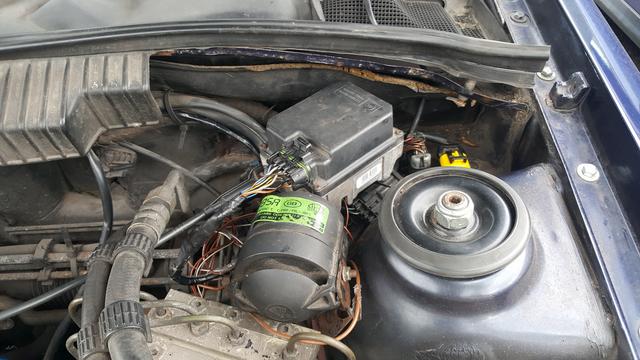
For me the hardest task is deciding where to mount the control module or Cruise Control ECU. This is up to your own poetic license.

On the whole, the process and wiring is identical, except that there are two different sets of modules.
You guessed it 4-pot and V6.
This is relevant as the speed pulses for a V6 are different to those for a standard 4 cylinder car.
Using the wrong module will cause the car to only allow cruise to engage at the wrong speed range.

From what I understand, the wiring for all modules between 1995 and 2002 are the same, however approx 2000 onward saw the use of fly-by-wire electronics, so wiring information may vary slightly dependent upon where you look in books and on-line.
From what I have read in various places, it appears that diesel fuelled Vectras and Omega had the cruise control built into the ECU, so no need for a separate module.

For my installation, I am using a 1995 4 Cylinder Vectra-B module.

Also - again, because it is me, I will be looking at ALL the wires in the system, not just the bare essentials.

I have a manual box (F18) on my car, but if you have an auto, then don't worry - I will post up the auto box wire information.

So to start with, I will post up all the wiring diagrams and connector views.
For information, the standard notation for Cruise Control is "CRC".
Do not confuse this with "CC", as this is for Check Control.

If you have a Haynes manual, then standard notations are.
AT = Auto Transmission
CLS= Clutch Switch
DIAG = Diagnostic Connector
INS = Instrument Cluster
MT = Manual Transmission
SLS = Stop Light Switch (Obviously brake light switch)
WEG = Road Speed Signal (Weg is German for wheel)

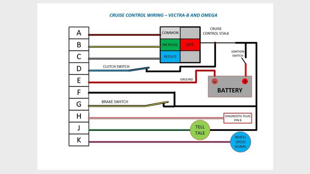
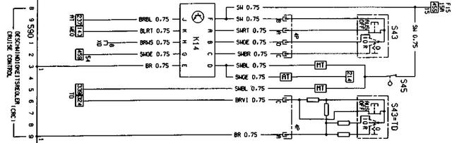
Firstly my simple-pimple diagram.
Note that N/C means the switch is normally closed (cuts the circuit when the switch is operated).
N/O means the switch is normally open (closes / makes the circuit when the switch is operated).

Image

An early Omega-B Haynes Diagram

Image

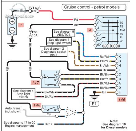
A Later Haynes Diagram

Image

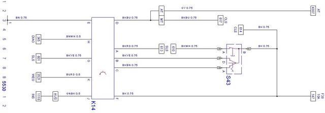
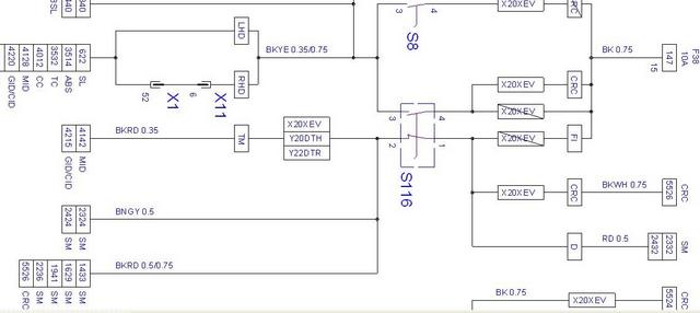
The TIS2000 Diagram for a Vectra-B

Image

Now for the Connectors!!

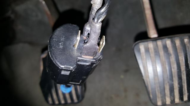
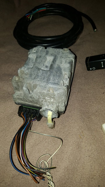
Here is a picture of the parts that you need.

Image

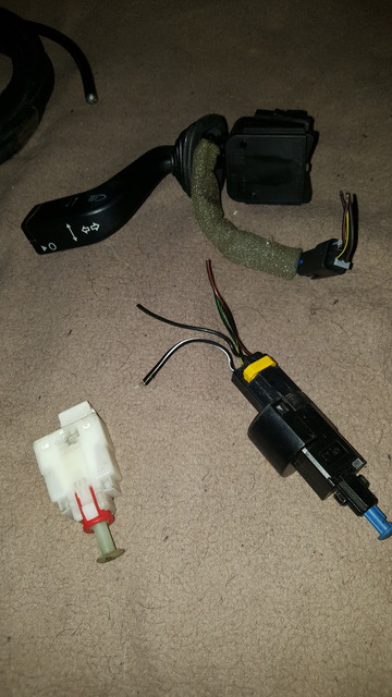
The main ten pin connector, which is the same as the ALDL diagnostic plug fitted all cars upto 1994..and phased out completely by 1996.

Image

Image

The brake switch.
Use the existing brake switch, and join the wire from module pin G to the black / yellow wire of the switch.
The 4 pin brake switch. (Use this for the Clutch Switch...

Image

And the brake switch circuit.
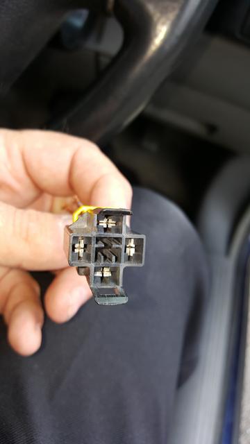
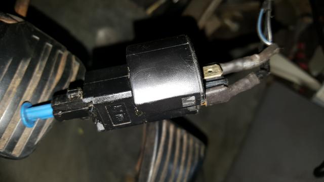
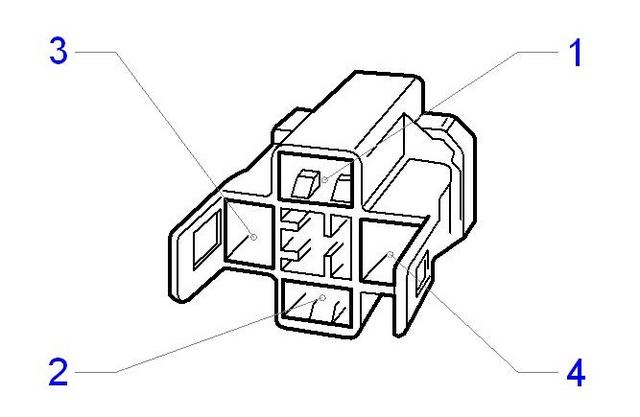
Image

The clutch switch.
Use the 4 pin brake switch for your clutch switch.
Ignore the white clutch switch in the image above. It will not fit a Cavalier.

Here is the wiring diagram for the switch.
In my diagram I said that the switch is normally open.
But the diagram below shows a normally closed switch. Both are sort of correct, as the switch at rest is an open circuit, however when the clutch pedal is at rest, it is pressing the switch into the closed position, due to the location of the switch in relation to the clutch pedal pivot point.
So the simple rule for this is - as we are wiring into a Cavalier, use two opposing pins in the clutch switch.
You will see a plastic "T" shaped peg at the bottom of the switch.
We want the pins above and below the "T" peg. The two pins either side can be ignored.
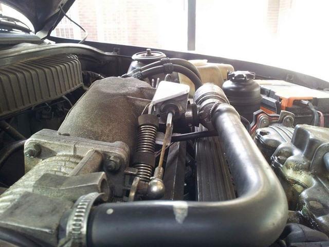
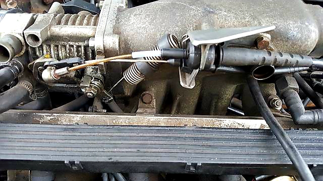
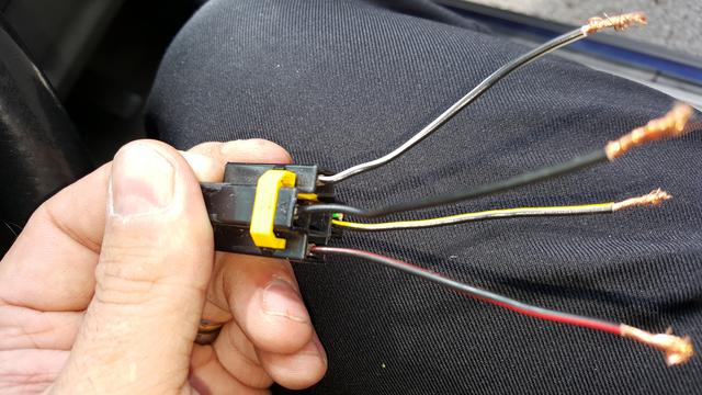
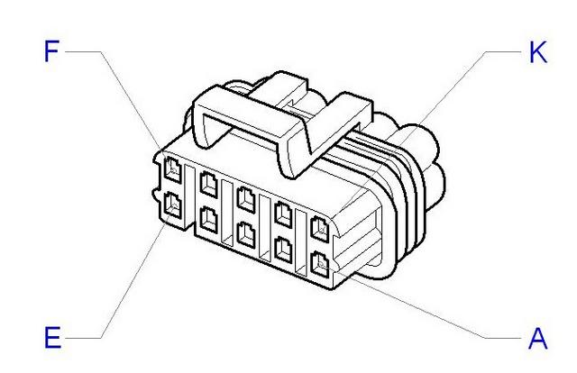
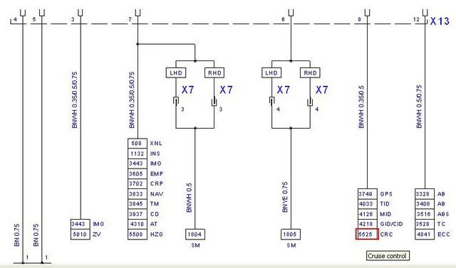
Image

The Stalk Switches.
The Cruise buttons on the stalk have a separate 4-wire flying lead.
Now in one of the diagrams (The official TIS2000 image), there is a bit of a blooper where it states that two pins are identified as pin A.
Ignore this, as there are pins A, B, C and D in the stalk connector.

Just use my colour diagram above to wire this up. (The coloured blocks in my diagram match the colours of the wires within the stalk flying lead)

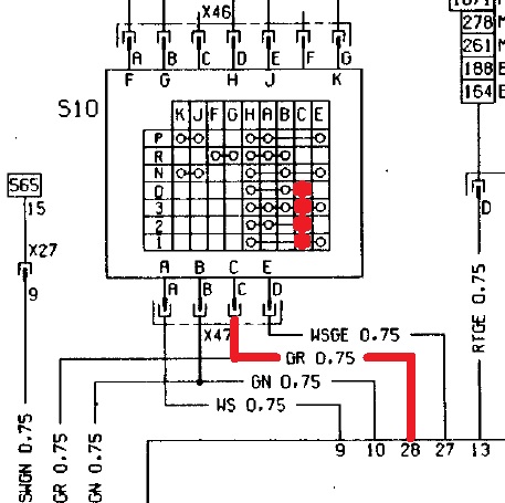
If you have an Auto-Box, then you need to connect the grey wire from the auto box switch in place of the clutch switch connection (It prevents the cruise from being engaged if not in one of the forward drive settings).
For clarity, this is module pin D

So first the schematic for the Vectra-B

Image

And the grey wire as fitted to the Cavalier / Vectra-A

Image

Now then - Two wires that people never seem to fit.
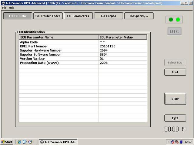
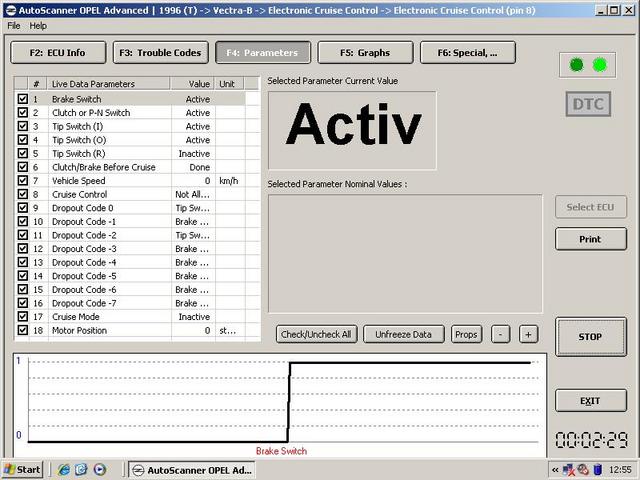
Diangostic Wire.
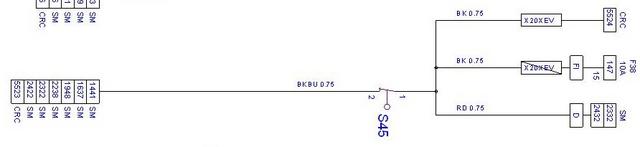
The most relevant if things go pear shaped is the diagnostic wire. Pin H

This will go to pin 8 of a 16 pin EOBD connector, to allow connection of your friendly Tech 2, OpCom / Vauxcom or AutoScanner diagnostic / programming tool. (Again this is the Vectra B schematic). It is possible to connect a test tool to your car, as long as you use: -
Pin 16 = +12 volt wire,
Pin 4 and / or pin 5 = ground wire(s) and
Pin 8 = the diagnostic wire.
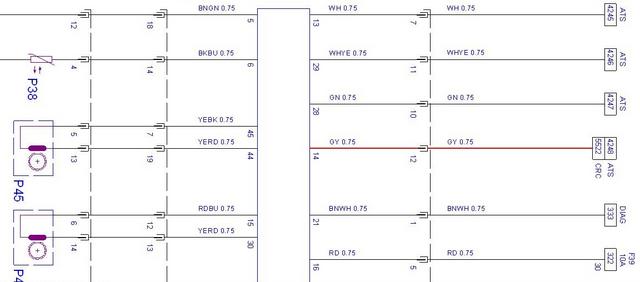
The diagram below shows the connections to pins 4,5 and 8 of the 16 pin connector.

Image

Dash Light
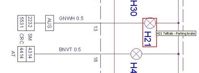
The final wire is the dash tell tale wire. Pin J

For some reason, in the Vectra-B, this was only fitted to "Australia" models. There is no mention at all in the Omega listing. Very odd.
Anyway - general gist is to have an ignition live supply to the tell tale bulb, and then the other wire is connected to the cruise control module.
My colour diagram shows this as wired independently from the instrument cluster.
If you were using the instrument cluster, then the cruise wire is connected to the hand brake tell tale pin.
This is the diagram below if connecting to the dash. (Vectra-B pin number shown)

Image

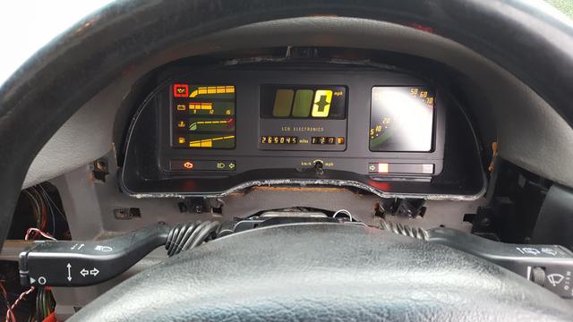
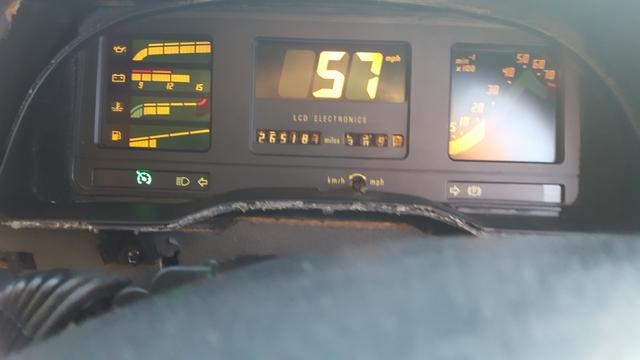
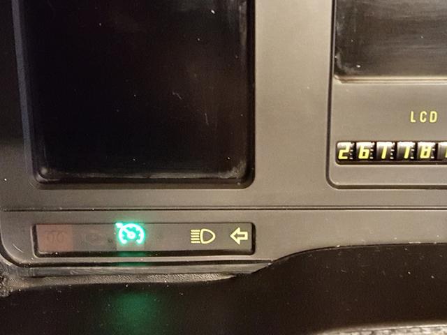
This is my tell tale wired in to my Astra GTE Digi Dash.
The emblem is from a Vectra-C speedo face sticker.

Image

I will continue this thread as my installation progresses...
Stay tuned.
User avatar
Robsey
Club Admin
Posts: 10596
Joined: Fri Dec 12, 2008 1:42 pm
Location: East Manchester

Re: Fitting Cruise Control to a Cav Mk3 - The electrics.

Post by Robsey »

After completing my installation,
I have come to a few conclusions.

1 - Be thorough when checking your wiring.
It took me three attempts to get mine right.
Having two black/yellow wires tripped me up despite checking continuity from each pin.

2 - Clutch Pedal Switch.
Get a 4 pin brake switch for a Cavalier or Vectra-B.
The 4 pins are arranged so that they operate as opposing pairs.
One pair is "on" when pressed.
The other pair is "off" when pressed.
This way, you can wire up the pedal switch to suit the cruise module.
It can get confusing.

3 - Do test each switch's operation before connecting up to the module.

See the next post for testing.
User avatar
Robsey
Club Admin
Posts: 10596
Joined: Fri Dec 12, 2008 1:42 pm
Location: East Manchester

Re: Fitting Cruise Control to a Cav Mk3 - The electrics.

Post by Robsey »

TESTING YOUR WIRING.

Test the connector with the module disconnected,

I put a 12volt test light across the pins as follows. (I used a 12 volt rated led).

Connect the "-" / minus side of the light to Pin E (connector ground pin).
Pin E is used to ground the light / led for all switch tests.

First test -
Connect the "+" / positive of the light to pin F to make sure you have ignition live and ground connections.
The light should illuminate as soon as the ignition is turned on.

At first mine didn't light up - I hadn't fitted the fuse in the piggy back after removing it on Friday. D'oh!!
I cut off the piggy back and wired straight into the fuse box (ignition live fuse slot).
Light now working.

Then test the other pins as follows: -
Connect the "+" / positive wire to each of the following pins in turn to test.
On is when the light illuminates (obviously).

A = The stalk "O" / Off button.
Off when Button pressed.
On when Button released. 


B = The stalk "I" / Increase or Set button.
On when Button pressed.
Off when Button released.

C = The stalk "R" / Reduce or Resume button.
On when Button pressed.
Off when Button released.

D = Clutch Pedal switch.
Off when Pedal pressed fully to the floor.
On whenPedal released.

G = Brake Pedal switch.
On when Pedal pressed only a short distance.
Off when Pedal released.

As for the other wires...

The Cruise tell tale is ignition live on one side.
And is earthed via the cruise module pin J
(Same pin as the auto-box grey wire).
On my plug, this was a white wire with a black stripe.

The blue / red wire from Cruise module pin K.
I connected this to my redundant dual info display plug wire of the same colour.
(I use the fuel computer in my car, hence why the dual info display is redundant).

You could use the blue/red wire from any of the following.
1 - Speedometer pin 3
2 - Radio pin 5
3 - DID pin 12
4 - Fuel Computer pin 21
User avatar
Robsey
Club Admin
Posts: 10596
Joined: Fri Dec 12, 2008 1:42 pm
Location: East Manchester

Re: Fitting Cruise Control to a Cav Mk3 - The electrics.

Post by Robsey »

As an update, from my OpelScanner thread. This shows the diagnostics wire (Pin H) working fine.
So as promised - ALL ten wires connected up and working :cool

Image

Image

And here is the diagnostics print-out for the Cruise Control.

Image
User avatar
Robsey
Club Admin
Posts: 10596
Joined: Fri Dec 12, 2008 1:42 pm
Location: East Manchester

Re: Fitting Cruise Control to a Cav Mk3 - The electrics.

Post by Robsey »

I have decided to add the physical installation part too. (Taken from my WIP).

On my C20NE, I had to modify the cable guide on the plenum (inlet manifold body).

My original bracket.

Image

The Omega bracket modified to suit.

Image

The modified bracket fitted.
Image

And all connected up.
Image

Squig had to do similar on his V6 install.
I think it is only the X20XEV mounted guides that do not need modification.
User avatar
Robsey
Club Admin
Posts: 10596
Joined: Fri Dec 12, 2008 1:42 pm
Location: East Manchester

Re: Fitting Cruise Control to a Cav Mk3 - The electrics.

Post by Robsey »

The cruise loom is wired in to the stalk and pedals, and the ignition live is connected to fuse 7.

Image

I fitted the actuator cable in the engine bay, and discovered that my throttle return spring was fitted wrong.
Now refitted correctly.

Image

I fitted the Vectra-B brake switch.
I checked the brake lights and found them to be on with the ignition on.

I refitted the Cavalier brake switch and fitted the Vectra-B switch as a clutch switch instead.
Normal brake light service resumed.

In an odd quirk, my original cavalier brake switch has only two pins... but three wires in the connector.

Still having the same issue, that I have had for years.
Due to having power steering, an alarm head and ABS, I was struggling to find a place to mount the cruise module.

I tried the bulkhead - too tight a bend for the cable.

I thought that I was probably looking at somewhere above the gearbox between the ABS unit and the battery.

Can't fit it any further back due to power steering hoses and abs pipework.
Hmm well, you'll see.
Looks like custom mounting brackets for the win.

And I finally sussed where the cruise module can go.

Image

I managed to make up a metal-strip bracket to support the module in this approx position, whilst sitting clear of any wiring looms, diagnostic socket and octane coding plug.

Hey presto - all working spot on.
Amazingly, it seems to work as low as 14mph all the way up to normal motorway speeds. I haven't tried above 75 mph, so cannot advise the top limit... if there is one.
Note - even the cruise light works!!

Image
User avatar
Robsey
Club Admin
Posts: 10596
Joined: Fri Dec 12, 2008 1:42 pm
Location: East Manchester

Re: Fitting Cruise Control to a Cav Mk3 - The electrics.

Post by Robsey »

Pedal Switches.

Clutch Pedal Switch.

Here is where the mounting hole is on the clutch pedal mounting frame.

Image

As for the wiring format.

The two pins are those above and below the "T" shaped plastic post.

So pins are.
BLACK
T
BLACK / BLUE.

The pins either side are not required.

Image

Image

Image

Image

The Brake Light.

Splice the black / yellow wire from the cruise module pin G to the black / yellow wire on the brake switch connector.
Locked