Yes indeed, I could make a bracket if need be but it would seem the V6 is the shorter cable and he advises the longer is best. Can't be many Omegas with 4 pot and then they probably won't have CC!
Edit, my bracket should be ok.
Have the images on the HOW2 dissappeared?
Wiring in Cav Mk3 Cruise Control - Discussion Thread.
Moderator: Robsey

Re: Wiring in Cav Mk3 Cruise Control - Discussion Thread.
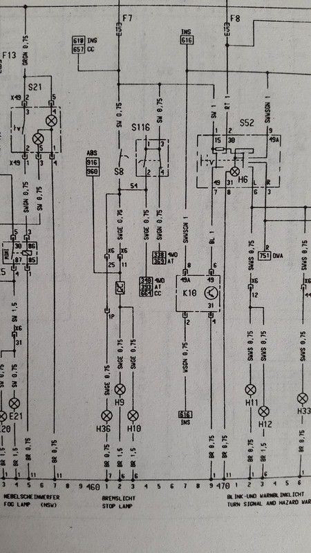
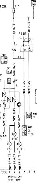
The wiring in the book of lies,
Where S8 and S116 both are called 'Stop light switch' - which is the one on the brake pedal?
(F7 fuse,H9, H10 and H36 are the bulbs)
Where S8 and S116 both are called 'Stop light switch' - which is the one on the brake pedal?
(F7 fuse,H9, H10 and H36 are the bulbs)
Re: Wiring in Cav Mk3 Cruise Control - Discussion Thread.
I don't think I have an Octane plug?
But I do have this, which should also be on the V6 Loom I have
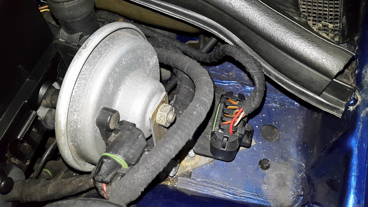
But I do have this, which should also be on the V6 Loom I have

Re: Wiring in Cav Mk3 Cruise Control - Discussion Thread.
Yep - that is the diagnostic plug.
Should do the job nicely.
I would keep as much loom as possible with the 10 pin socket.
That will allow you to be able to have enough wire to reach into the cabin area, where you can then extend the loom and hide the join up behind the glove box.
The usual recommendation is to get a 7 wire caravan / trailer wire and run this from the 10 pin socket to the switches and pedals.
The only down side to this is that the outer insulation on the cable can make the whole thing bulky and awkward.
I have a complete Vectra-C interior loom that I use for hacking out entire cable runs for my projects. Not as bulky or unsightly.
Re: Wiring in Cav Mk3 Cruise Control - Discussion Thread.
Regarding brake light switches.
As you can see, they are both correct dependent upon what equipment your car has.
The deciding factor appears to be if you have check control.
If you do have check control, then S116 is correct - it is the 4 pin switch.
If you don't have the check control loom, then you only need a 2 pin switch, and so in that case S8 is correct.
Re: Wiring in Cav Mk3 Cruise Control - Discussion Thread.
Ok great. Thanks again.
Yes i can see this loom coming in handy.
Stuns me how it fills the garage floor laid out!
I have check control so that will be a 4 pin requirement then.
I have purchased the Omega unit you linked to above Robsey and will assess it. Another may come up but if I dont buy it another won't!
I am also asking the seller what else he can remove me from another Omega he is breaking.
Re: Wiring in Cav Mk3 Cruise Control - Discussion Thread.
Just looked at your cable guide photo above.
I wonder if that rectangular hole will do for fitting the actuator cable outer sleeve to.
It would save you some cutting and shutting.
If you do get all Omega stuff, it may need reprogramming (very early Tech 2 or maybe even very late VauxCom / OpCom) to change variance settings to suit your engine format.
Re: Wiring in Cav Mk3 Cruise Control - Discussion Thread.
Yes that's what I meant, would be handyRobsey wrote:I wonder if that rectangular hole will do for fitting the actuator cable outer sleeve to.
What do you mean by ALL Omega stuff, thought the only part that needs reprogramming would be the control module from 6 cylinder to 4? The switches/stalk/loom plugs are the same?Robsey wrote:If you do get all Omega stuff, it may need reprogramming to change variance settings to suit your engine format.
Re: Wiring in Cav Mk3 Cruise Control - Discussion Thread.
Okey dokey.
For clarification - It is only the module that may need programming.
Maybe I should wait until I am fully awake when answering posts.
As for parts being the same...
I understand the Omega control cable is shorter than the Vectra cable.
The Omega / Vectra clutch switches are available in a few different formats.
Otherwise, yes all other parts are the same.
Re: Wiring in Cav Mk3 Cruise Control - Discussion Thread.
I have just read the article from Total Vauxhall magazine dated 20/2/2009.
(I have it saved on my laptop in pdf format).
It states -
Throttle cable mount. -
Other models such as C20XE engined cars already have a mount in place for the cable.
And for convenience -
Clutch pedal switch.
On Cavaliers mk2 and mk3, Astra-mk3 and Calibras - a standard brake switch can be used and there is a bracket on the clutch pedal to twist the switch into.
So for me that makes things simple.
1 - Transfer the two wires from the current brake switch to the four pin brake switch.
This will need two wires removing from the 4 pin switch to make way for the two transferred wires.
2 - the two redundant wires formerly from the 4 pin brake switch can be fitted to the two pin brake switch - and then wired up for the clutch switch.
I much prefer to move wires than to start cutting and shutting to achieve the same end result.
Re: Wiring in Cav Mk3 Cruise Control - Discussion Thread.
Very much agree, cutting and joining is a pain!
I have seen a link to that article on a post on here, but the link is broken...
Searching the 'net give several broken non working links too...
Any chance of looking why the images have vanished on the HOW2 page for this Cruise?
May help because I'm not sure if I need the plug that plugs in to the Cruise control indicator stalk from a donor car and replace the one on my car? The CC stalk has more terminal connectors doesn't it?
Re: Wiring in Cav Mk3 Cruise Control - Discussion Thread.
If you pm me your email address, I can send you the article mentioned in the link.
It will be a pdf if that is okay.
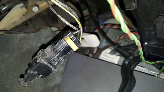
The cruise control stalk has a separate plug with 4 wires in it.
1 each for
"I" (set),
"R" (resume),
"0" (off)
and a common wire.
As for my How 2...
All links now repaired (again).
It will be a pdf if that is okay.
The cruise control stalk has a separate plug with 4 wires in it.
1 each for
"I" (set),
"R" (resume),
"0" (off)
and a common wire.
As for my How 2...
All links now repaired (again).
Re: Wiring in Cav Mk3 Cruise Control - Discussion Thread.
For those who did not notice...
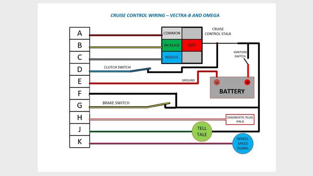
I have corrected an error on my "simple layout" image.
The first image of the whole thread.
I had my module pins F and G the wrong way round.
They are correct now.
Ignition live - black on F
Switched live - black / yellow on G.
Further update - if you have the four pin brake switch, then there are two "extra" wires going from the brake switch.
1 to fused live. (Black)
2 that go to the cruise module. (Black / red and Black / Yellow)
and one to the stalk common pin. (Black / white).
If you have only a 2 pin brake switch, connect the black / red from the cruise module pin a direct to the common pin of the stalk.
Re: Wiring in Cav Mk3 Cruise Control - Discussion Thread.
Pulled out the boxes of toys from my shed today.
All the lovely connectors for the cruise control system.
Strangely, every time I look at the wiring diagrams, they look to be configured slightly differently.
The observation tonight was the brake switch (4 pin) is said to be in series with the wire to pin A of the cruise equipped stalk.
This is not mentioned in the other How 2s on the web.
Re: Wiring in Cav Mk3 Cruise Control - Discussion Thread.
Now then my friends, because I like taking a hit for the team, I decided to look at what the brake switch is like on my car.
Not the most comfortable task to twist your head and shoulders under the dash.
Anyway I discovered that on my 1994 LSi spec car, that I had 3 wires.
A - Black - Ignition live feed from fuse 7
B - Black/Yellow - switched live to brake lights.
C - Black/Green - switched live to 4 wheel drive and auto-box. Which is odd as I have neither on my car.
In appearance, it is identical to the standard Vectra-B, Omega-B etc four pin brake light switch.
And here is the schematic for the Cavalier switch.
S8 is the standard 2 wire brake pedal switch.
S116 is the 4 pin (3 wire) brake pedal switch.
Further observations revealed that when the brake pedal is pressed, the switch plunger is allowed to extend.
BUT
Due to the pivot position on the clutch pedal, the switch plunger is pressed when the clutch pedal is pressed.
On the Cavalier, as the performance Vauxhall article reports (and Squig's How 2), a standard Vauxhall brake light switch will fit into the slotted hole in the clutch pedal bracket.
A standard twist-in bayonet fitting.
The white clutch switch used on Omegas as shown in the article and my earlier photos will NOT fit the Cavalier clutch pedal.
Re: Wiring in Cav Mk3 Cruise Control - Discussion Thread.
A further comment on the brake / clutch switches.
You can use standard female (6.3mm) Lucar / spade connectors to plug onto the legs of the switches.
I am thinking of making up a mini adapter (daisy-chain) loom to go between the body loom and brake switch.
This way, it can all be reverted back to standard if necessary without any major hacking of the loom.
It is also suggested in various How 2s, to run across the back of the engine bay,
Then through the bulk head behind the brake servo.
Down the back of the dash to the instruments, stalk and
Down to the pedals.
Pretty simple I suppose.
But the glove box still needs to come out to allow marking out and drilling for mounting screws if you are attaching the cruise module to the bulkhead. There is a rectangular recess that appears to "indicate" a possible location.
Re: Wiring in Cav Mk3 Cruise Control - Discussion Thread.
So the soldering begins.
I have used a scrap Vectra-C rear floor pan loom to get wires of the correct colour, which I thought would look more pukka than a 7 core trailer loom.
As per my usual methodology,
I strip about 10mm of insulation from the end of each wire.
Then twist them together, trying to keep them looking tidy and even.
(Blue / black wire farthest right)
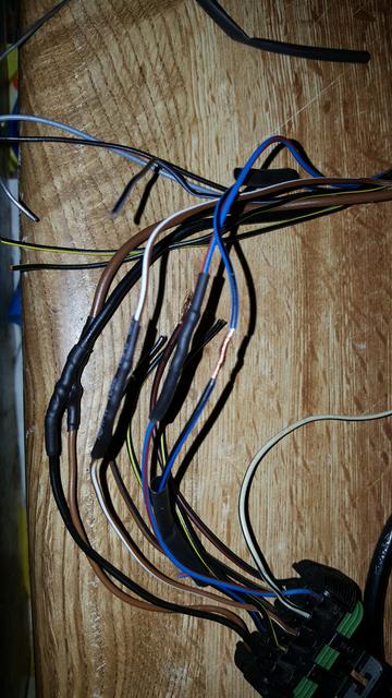
Then solder to ensure a secure permanent joint.
Then sleeve with two layers of heat shrink tubing.
Two layers are not necessary, but I am a tad O.C.D.
To be honest, there will be three layers, however the third layer is used to bind all ten joints as tidily as possible.
I am starting the loom now, ready to install and test next week.
Eek - so much to do....
I will need to check wire continuity, as I have two black / yellows in the loom, and they will not work if fitted the wrong way round.
More images later...
I have used a scrap Vectra-C rear floor pan loom to get wires of the correct colour, which I thought would look more pukka than a 7 core trailer loom.
As per my usual methodology,
I strip about 10mm of insulation from the end of each wire.
Then twist them together, trying to keep them looking tidy and even.
(Blue / black wire farthest right)
Then solder to ensure a secure permanent joint.
Then sleeve with two layers of heat shrink tubing.
Two layers are not necessary, but I am a tad O.C.D.
To be honest, there will be three layers, however the third layer is used to bind all ten joints as tidily as possible.
I am starting the loom now, ready to install and test next week.
Eek - so much to do....
I will need to check wire continuity, as I have two black / yellows in the loom, and they will not work if fitted the wrong way round.
More images later...
Re: Wiring in Cav Mk3 Cruise Control - Discussion Thread.
Damn ... cool. So where’s the queue. I’d like one!
Re: Wiring in Cav Mk3 Cruise Control - Discussion Thread.
It has taken me nigh on ten years to pull my finger out and start this modification.
I discovered that I have already done my stalk loom, so we are about 80% done wiring-wise.
I also continuity checked my black / yellows, so now I know which goes to the stalk, and which goes to the brake pedal.
I discovered that I have already done my stalk loom, so we are about 80% done wiring-wise.
I also continuity checked my black / yellows, so now I know which goes to the stalk, and which goes to the brake pedal.
Re: Wiring in Cav Mk3 Cruise Control - Discussion Thread.
Okay so the loom is all but ready to fit.
There are 4 wires to sort when the car's dash is stripped.
Actually only 2 wires are dash related.
Speed pulse and tell tale.
The other 2 stay in the engine bay
Main earth and diagnostic wire.
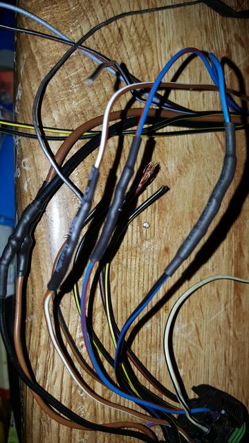
So - engine bay end is the main plug.
And the coil below it is for the diagnostics connector (3 wires to EOBD II plug - pins 5, 7 and 16).

The blue and the grey wires are for speed pulse and tell tale light on the dash.
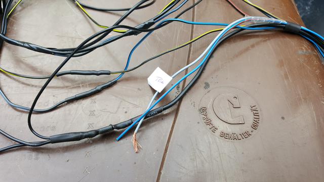
And this lot below is the stalk loom and the loom to the clutch and brake pedals.
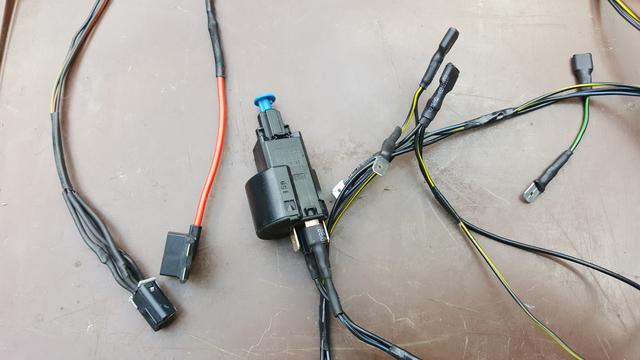
The red wire is a piggy back fused feed that will plug into the Fuse 7 slot.
If you are wondering what the short black / green wire is to the far right,
it is one wire on my existing brake loom,
I plan to "daisy chain" my cruise loom between the brake switch and it's connector so that it can be removed at a later date and it also means that I am not hacking into original wiring.
Because of this I need to fit a straight link to maintain the function of the black / green wire even though I am sure that it is only for 4x4 and auto box functions.
Neither of which are fitted to my car.
As such,
It is mainly a matter of running the wire across the bulkhead, through to the back of the dash and plug in the stalk and pedal switch connectors.
Then as soon as I terminate and wire up the main earth and speed pulse wires, the sytem is wired to mimimum requirement to work.
The remaining two wires - diagnostic and tell tale are optional, and so could be left undone, or fitted at a later date if time gets tight.
There are 4 wires to sort when the car's dash is stripped.
Actually only 2 wires are dash related.
Speed pulse and tell tale.
The other 2 stay in the engine bay
Main earth and diagnostic wire.
So - engine bay end is the main plug.
And the coil below it is for the diagnostics connector (3 wires to EOBD II plug - pins 5, 7 and 16).
The blue and the grey wires are for speed pulse and tell tale light on the dash.
And this lot below is the stalk loom and the loom to the clutch and brake pedals.
The red wire is a piggy back fused feed that will plug into the Fuse 7 slot.
If you are wondering what the short black / green wire is to the far right,
it is one wire on my existing brake loom,
I plan to "daisy chain" my cruise loom between the brake switch and it's connector so that it can be removed at a later date and it also means that I am not hacking into original wiring.
Because of this I need to fit a straight link to maintain the function of the black / green wire even though I am sure that it is only for 4x4 and auto box functions.
Neither of which are fitted to my car.
As such,
It is mainly a matter of running the wire across the bulkhead, through to the back of the dash and plug in the stalk and pedal switch connectors.
Then as soon as I terminate and wire up the main earth and speed pulse wires, the sytem is wired to mimimum requirement to work.
The remaining two wires - diagnostic and tell tale are optional, and so could be left undone, or fitted at a later date if time gets tight.
Re: Wiring in Cav Mk3 Cruise Control - Discussion Thread.
I have realised that I have put a wire in that I did not need.
To clarify - There is a wire from Fuse 7 direct to the black wire on the brake pedal switch.
In my loom today, the main ignition live feed goes from a piggy back fuse carrier fitted to fuse slot 7.
The main ignition live wire then splits off to feed the clutch pedal and stalk.
The main wire then goes onward to the cruise module.
This is the un-necessary bit -
I have put a black link wire between the clutch pedal switch and brake pedal switch.
As the main brake circuit and my cruise circuit will both be powered from Fuse 7, it appears that I now have a duplicated feed.
Hopefully this will not cause any "loop back" issues.
If it does, it will be a simple matter of wire cutters to the rescue.
Hopefully Gary - you will "like" more when I have it fitted and working.
Only 4 1/2 weeks to VBOA.
Re: Wiring in Cav Mk3 Cruise Control - Discussion Thread.
Main loom is now installed into the engine bay.
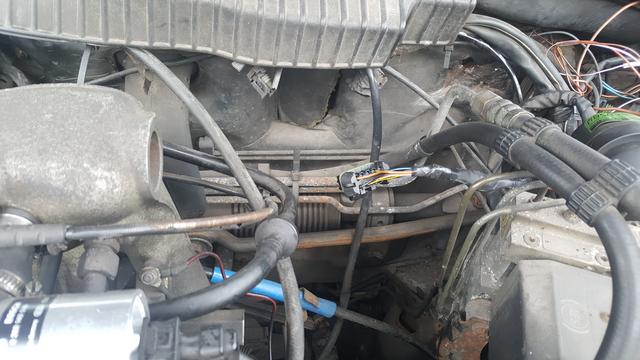
Wires are inserted through the bulkhead where the speedo cable goes.
I have an electronic speedo transducer.
The instruments, radio, heater panel, ash tray, glove box and centre console are all out to allow full access to the dash looms.
Wires are inserted through the bulkhead where the speedo cable goes.
I have an electronic speedo transducer.
The instruments, radio, heater panel, ash tray, glove box and centre console are all out to allow full access to the dash looms.
Re: Wiring in Cav Mk3 Cruise Control - Discussion Thread.
On my car,
Due to having ABS and power steering and an alarm head,
This was the only place that I could get it to fit...
Just need to make up some jaunty brackets to make it more secure.
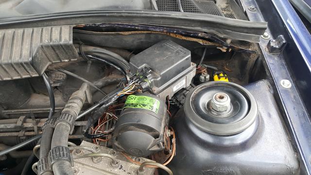
UPDATE - This is proving quite problematic as there are looms passing behind and below the module -
Looks like my alarm will need to be moved more inboard onto the bulkhead.
Tried modifying the metal cage that the cruise module normally sits in, but it is not really going to fit effectively. Too bulky and just the wrong shape.
It will probably need mounting using slotted strips of steel like you would use to hang a third party radio, oldie worldie exhaust hanger clamp or aftermarket door lock solenoids.
Due to having ABS and power steering and an alarm head,
This was the only place that I could get it to fit...
Just need to make up some jaunty brackets to make it more secure.
UPDATE - This is proving quite problematic as there are looms passing behind and below the module -
Looks like my alarm will need to be moved more inboard onto the bulkhead.
Tried modifying the metal cage that the cruise module normally sits in, but it is not really going to fit effectively. Too bulky and just the wrong shape.
It will probably need mounting using slotted strips of steel like you would use to hang a third party radio, oldie worldie exhaust hanger clamp or aftermarket door lock solenoids.