
This thread is for any questions or comments about this How 2.
viewtopic.php?f=15&t=16507
As you can see, my switch panel was for the more common two window switch panel, although the four pin unit is very similar, but obviously more switches and leds.
Stripping Electric Window Switches. Discussion Thread.
Moderator: Robsey
Re: Stripping Electric Window Switches. Discussion Thread.
Okay continuing on from the How 2, and my comments of finding an output voltage to match when the switch led's are illuminated -
The legs / pins / wires that link to the led's appear to be quite easy to see when you strip down to expose the copper tracks.
They are the pins that I have soldered 2 extra wires to.
This was a bit faffy due to not having any full height brass pins. Just cropped down strips poking just above the underside of the plastic body of the switch assembly.
This makes soldering fun, as you run the risk of melting plastic before you melt the solder.
So here goes.
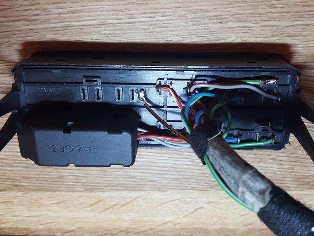
1 - the brown / black wire on the far left of the image is the ground or "-" side of the led.
2 - the grey / green on the far top right of the image is the feed or "+" of the led.
I have not tested it yet, but it appears that pin (2) is also the +12 volt feed to the window motor switches.
(Unswitched side of the rockers).
Part of my test will be to see if it is battery voltage, or a reduced voltage to suit the led's. (Nearer 2.5 to 3.3 volts).
I will suss this out when I can find my pc power supply. Great for car test projects
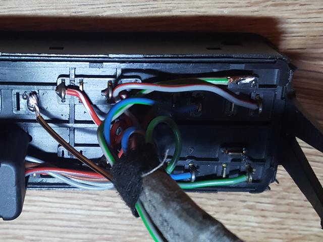
The legs / pins / wires that link to the led's appear to be quite easy to see when you strip down to expose the copper tracks.
They are the pins that I have soldered 2 extra wires to.
This was a bit faffy due to not having any full height brass pins. Just cropped down strips poking just above the underside of the plastic body of the switch assembly.
This makes soldering fun, as you run the risk of melting plastic before you melt the solder.
So here goes.
1 - the brown / black wire on the far left of the image is the ground or "-" side of the led.
2 - the grey / green on the far top right of the image is the feed or "+" of the led.
I have not tested it yet, but it appears that pin (2) is also the +12 volt feed to the window motor switches.
(Unswitched side of the rockers).
Part of my test will be to see if it is battery voltage, or a reduced voltage to suit the led's. (Nearer 2.5 to 3.3 volts).
I will suss this out when I can find my pc power supply. Great for car test projects
Re: Stripping Electric Window Switches. Discussion Thread.
I know I'm raising the dead here but it's a discussion thread after all. I'm on the job of stripping all nooks and crannies in the car and converting to LED so I came to these switches and I noticed you are mentioning that these original yellow-ish/orange-ish bulbs are LED. How come they don't have a resistor soldered with them and now if I want to solder an LED in the same spot I have to solder the resistor. For a discussion sake I have unsoldered this OEM bulb and connected it to a voltage regulator (1V-24V) and I regulated voltage from 1V to 24V and it's emitting the light with no problems on any voltage from dim to bright. Would it be wrong to say that these are not LED but ordinary bulbs although they look like LED ?
Re: Stripping Electric Window Switches. Discussion Thread.
I have looked at the Haynes manual and TIS2000, and both clearly show the symbols for LEDs and resistors on the wiring diagrams.
Maybe the resistors are inside the black block at the back of the switch where all the wires go in.
Maybe the resistors are inside the black block at the back of the switch where all the wires go in.
-
Tobias_CDX
- Registered user
- Posts: 111
- Joined: Thu Jun 15, 2017 10:43 am
- Location: Leipzig
- Contact:
Re: Stripping Electric Window Switches. Discussion Thread.
These are special 12-V-LEDs where any resistors are inside the LED.