Project - Retro-Fit a CD Changer

Post queries regarding your Mk3 Cavalier's ICE and electrical components (head units, wiring, retro-fit toys, upgrades etc.) here

Moderator: Robsey

Post Reply
User avatar
Robsey
Club Admin
Posts: 10619
Joined: Fri Dec 12, 2008 1:42 pm
Location: East Manchester

Project - Retro-Fit a CD Changer

Post by Robsey »

Since acquiring a Philips SC804 for a very low price, I became intrigued by the possibility of adding a 6 disc CD Changer.

The standard compatible CD changer at that time was the Philips DC 012.

This was a cost option on high end Cavalier Mk3, Calibra, Astra-G, and pre-facelift Omega-B, as well as similar aged Renaults and Jaguars.

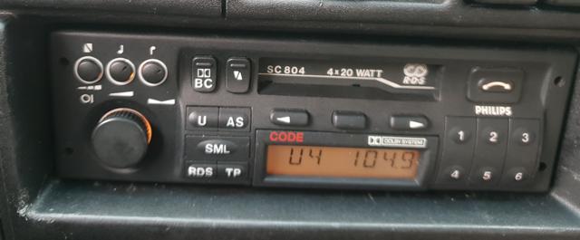
Now then - my SC804 does NOT have the CD button on its facia, but it does use a button with a long curved arrow for eject and mode change. It is a VERY early model. ( 90 355 878 ).

Image

Chances are that I am wasting my time.
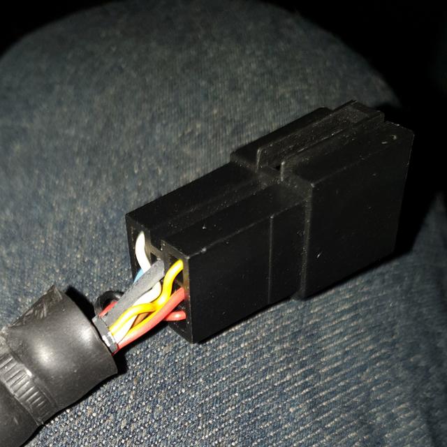
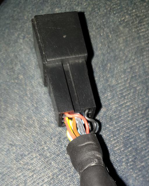
BUT - the rear sockets are all fully populated.

Image

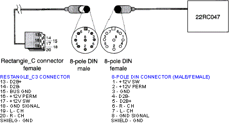
On the Grundig units, the un-used pins are often omitted at the factory.
The speed dependent volume control and telemute pins are missing on my SC303.

But perhaps Philips fully populate all sockets regardless of actual functions available.

Who knows, but what the heck...
Only one way to find out.

So lets begin...

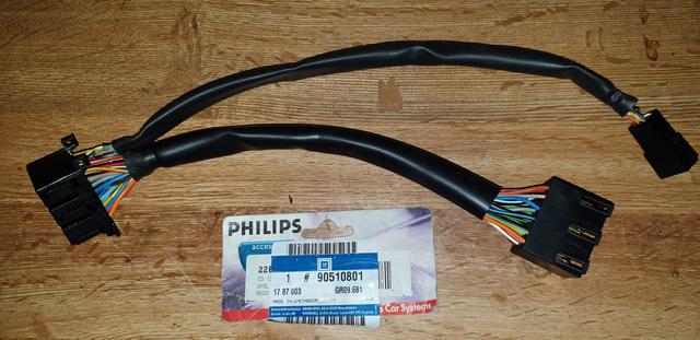
First - I was able to source an unused head unit lead.
In simple terms it is an adapter lead that daisy-chains between the body loom and the radio.

Part Number is. 90 510 801.
And shock horror, it is made in the UK!! :o

Image
User avatar
Robsey
Club Admin
Posts: 10619
Joined: Fri Dec 12, 2008 1:42 pm
Location: East Manchester

Project - Retro-Fit a CD Changer

Post by Robsey »

To my dismay, I noticed that it had a rectangular connector on the end, that I have only seen on Vauxhall looms.

Also, just to confuse matters, the wire colours do not match any official documents.

Image

Image

However on closer inspection, I have found that it will take a standard blue ISO mini-pin block connector as used on various makes to connect a CD changer.

Makes such as Dayton VDO, VW / Audi (various 90's Golfs, and late 90's Vauxhalls and the like.)

Now then, I happen to have a VDO 6 disc changer, left over from having my Dayton VDO MS4150 sat nav radio installed last year.
It is complete with a compatible 5 metre cable from the glove box to the boot.

I have yet to test the theory...
But if it works, I will only need an Astra-F / G, or Corsa-B radio cage to take the larger ISO plug.

So - I could leave the technical stuff there, but I am going to give a full info write up, for those that do have an SC804 with the CD button and fancy their chances.
User avatar
Robsey
Club Admin
Posts: 10619
Joined: Fri Dec 12, 2008 1:42 pm
Location: East Manchester

Re: Project - Retro-Fit a CD Changer

Post by Robsey »

The Technical Bit.

Firstly, the pin out pictures.

The three block ISO connector fitted to pre-CANbus Vauxhalls.

Image

The image is numbered as per Vauxhall notation, but does not distinguish between left and right channels
Pin 21 is left.
Pin 26 is right.

For the real boffins, this is a standard changer cable format.

Image

A bit confusing, but I will clarify things as I progress.

I have seen some Vauxhall changers and leads with the rectangular plug on all connections... not the rounded "din" connector.

Normally though, the radio end is rectangular mini-ISO,
and the changer end is the rounded din.
User avatar
Robsey
Club Admin
Posts: 10619
Joined: Fri Dec 12, 2008 1:42 pm
Location: East Manchester

Re: Project - Retro-Fit a CD Changer

Post by Robsey »

So wires from the radio connector.

Bottom Block of 8 Pins. (1 to 8)

Pin 4 for Ground
Pin 7 for antenna live feed.
Pin 8 for battery live feed.
(3 wires).

Top Block of 10 Pins (17 to 26)
Pin 20 - Outer sheath - Audio ground for left and right.
Pin 21 - Audio left channel
Pin 24 - Changer Data reference line.
Pin 25 - Changer Data signal line.
Pin 26 - Audio right channel.
(5 wires).

Should be 8 wires altogether.
User avatar
Robsey
Club Admin
Posts: 10619
Joined: Fri Dec 12, 2008 1:42 pm
Location: East Manchester

Re: Project - Retro-Fit a CD Changer

Post by Robsey »

My adapter loom, converts the wiring to match later ISO format

This is the later format as used on my Dayton VDO MS4150 radio.
We are interested only in the blue block.
Connector C3, for the CD changer.


Image

I do suspect however that pins 18, 19 and 20 are not correct.
I get : -
13 = CDC data +
14 = CDC data -
15 = data ground and chassis ground.
16 = battery live
17 = aerial amplifier 12v feed.
18 = audio common return.
19 = left audio in
20 = right audio in

Apologies to show this image again, but it does confirm my findings.

Image
User avatar
Robsey
Club Admin
Posts: 10619
Joined: Fri Dec 12, 2008 1:42 pm
Location: East Manchester

Re: Project - Retro-Fit a CD Changer

Post by Robsey »

If you are wiring from scratch, and making up your own cable, here is the route of each wire.

Starting at the radio plug.
Then depending upon your multi changer, you have the choice of the rectangular mini ISO connector, or the round Din plug.

I have included the wire colours as detailed in Haynes manual (for an Omega) and the bizarre colours of the GM adapter loom.

Image

It will be a couple of weeks before I report back about my attempts to add CDC.

I have to get the car MOT ready first, and it will be having a holiday in the garage, all next week.
User avatar
Envoy CDX
Club Admin
Posts: 9680
Joined: Sun Sep 23, 2007 3:51 pm
Location: Jarrow, Newcastle Upon Tyne

Re: Project - Retro-Fit a CD Changer

Post by Envoy CDX »

Nice one! Alot of information there to taken in Rob.
Check the Rules!

Raw 8v Power! - Bad Cav, Naughty Cav... Cav want's to do 90!

The How2 Index
User avatar
Robsey
Club Admin
Posts: 10619
Joined: Fri Dec 12, 2008 1:42 pm
Location: East Manchester

Re: Project - Retro-Fit a CD Changer

Post by Robsey »

You know me Gary,
I do try to be as thorough as possible.

Nothing worse than being unable to find that last nugget of info.
User avatar
Robsey
Club Admin
Posts: 10619
Joined: Fri Dec 12, 2008 1:42 pm
Location: East Manchester

Re: Project - Retro-Fit a CD Changer

Post by Robsey »

For added meaty goodness, I have finally found out what the pins in the 7-pin vertical connector do.

They are the outputs to an amplifier.
(From top to bottom)
Referred to as Connector D.
Pin 1 - Switched Live
Pin 2 - Return + (?)
Pin 3 - Signal Ground.
Pin 4 - Front Right.
Pin 5 - Rear Right.
Pin 6 - Front Left.
Pin 7 - Rear Left.
User avatar
Robsey
Club Admin
Posts: 10619
Joined: Fri Dec 12, 2008 1:42 pm
Location: East Manchester

Re: Project - Retro-Fit a CD Changer

Post by Robsey »

Looking further into Philips Radio Information on the "Technomagazin" website, it implies in a very vague way, that all SC804D(C) with serial numbers starting GM1804 are changer compatible, but units with GM0804 are not.

This is how I understand / interpret the blurb, so apologies if I am talking rubbish.
(Mistaken).

Bizarrely all units without integral display are listed as compatible.

"With integral display" is referenced by the "D" after the model number.

Initially it was assumed that the suffix (C) just referred to the unit having an integral cassette player mechanism, however on reflection, the "SC" prefix should infer "Stereo Cassette" unit.

So more research needed.

Having just checked my radio's serial number and it says *GM1804N9.......
Oooh - now that would be nice if......
User avatar
Robsey
Club Admin
Posts: 10619
Joined: Fri Dec 12, 2008 1:42 pm
Location: East Manchester

Re: Project - Retro-Fit a CD Changer

Post by Robsey »

So here is the interesting bit.

The CD changer powers up, but is not selectable from the radio head unit.

Hmm - I wonder if it is possible to "retro fit" a CD selection button.?

More research is required.
I have repair schematics for the early SC804 without CD button, so I will have to trace through all the gubbins to see what I can find out.

And then pull the front off the radio again to see if I can find any suitable connection points for wiring to a remote switch.

I really enjoy this type of challenge. :ugeek:
User avatar
Robsey
Club Admin
Posts: 10619
Joined: Fri Dec 12, 2008 1:42 pm
Location: East Manchester

Re: Project - Retro-Fit a CD Changer

Post by Robsey »

Took the front off the radio, and I cannot see anywhere for a CD button to be wired in.

So that is that.
I think the changer powered up as there was a 12v permanent live, antenna live and a ground all being fed directly from the main bottom ISO power connector block.

No easy way of checking for cd changer feeds from the top 10 pin block without an oscilloscope to verify the presence of voltages, pulses or wave forns.

That said,
There is nothing to say that my issues could be to do with using a VDO changer rather than the Philips DC012 as Vauxhall intended.

And also,
I haven't checked the main circuit board for connections to the 'ISO block C' socket, or for switch input tracks.
The schematic diagram does not mention CD changer at all. Or at least, not from what I can tell.

I cannot find a schematic for a SC804 with a CD button on it.
Post Reply