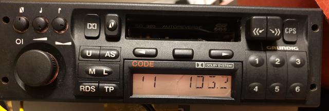
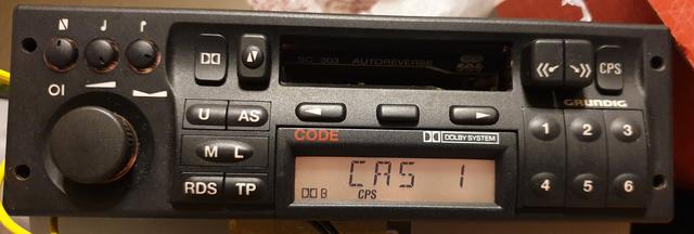
What is inside a Chip Display?

Post queries regarding your Mk3 Cavalier's ICE and electrical components (head units, wiring, retro-fit toys, upgrades etc.) here

Moderator: Robsey

Post Reply
User avatar
Robsey
Club Admin
Posts: 10619
Joined: Fri Dec 12, 2008 1:42 pm
Location: East Manchester

What is inside a Chip Display?

Post by Robsey »

I am just going to give a brief over-view of a typical chip display as fitted to standard Cavalier radios.

Grundig SC303,
Philips SC201,
Philips SC804...
and possibly the CD300, but it is too long ago since I had one to remember if it had a detachable display.

Image

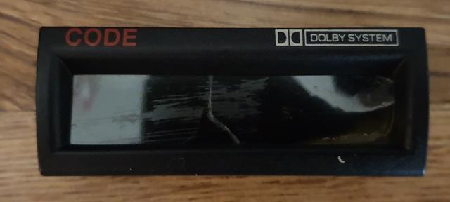
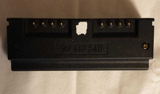
Part number 90 418 560.

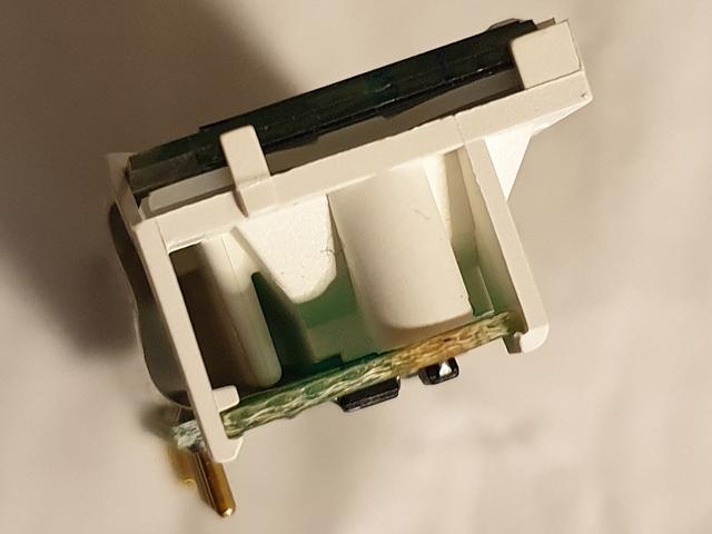
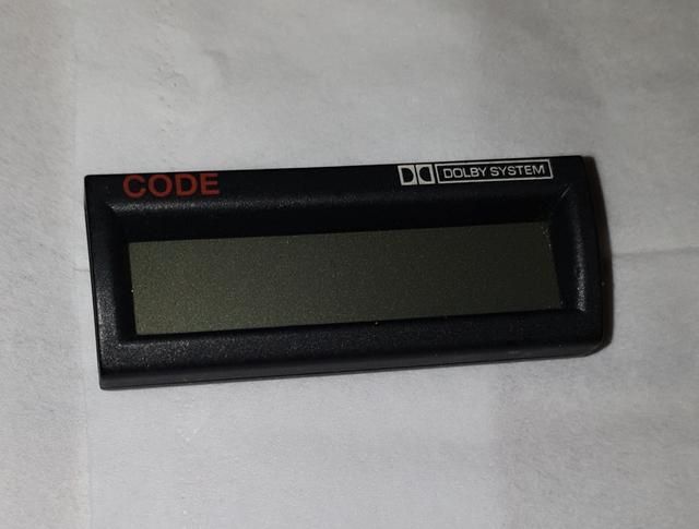
As suspected it is a very simple item which can be stripped down as follows.

First turn the display face down on a clean surface.

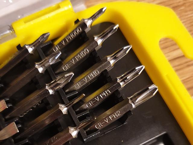
And remove two very tiny cross-head / Philips size 0 screws.

Image
Image

Image

You then need to run your thumb nail along the split across the top and bottom of the casing to tease the two shell halves apart.

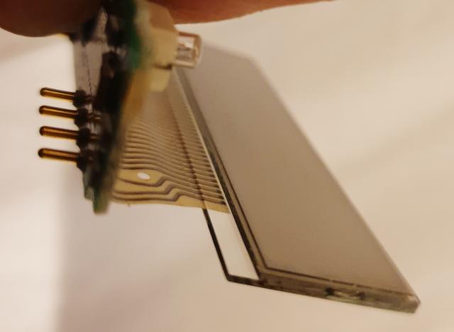
The front facia unclips to give this

Image

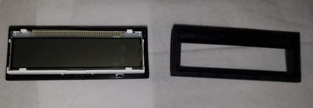
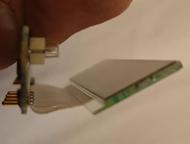
Then slip the complete internals out from the rear casing.
User avatar
Robsey
Club Admin
Posts: 10619
Joined: Fri Dec 12, 2008 1:42 pm
Location: East Manchester

Re: What is inside a Chip Display?

Post by Robsey »

The internals of the display is wrapped around a white plastic body.

Image

The display screen and colour filters are clipped to the front by four hooks / tabs.

And the circuit board is clipped to the rear by four hooks / tabs.

Be careful teasing the tabs open, as the plastic is quite old and brittle.

Once the internals are separated out, you will end up with all this.

Image

This is the display end.

Image

And this is the three tiny lights on the circuit board.

Image

I have zoomed into all the tracks of the ribbon cable, and all the solder joints, but I could not see why this particular display did not work properly, with missing and ghosting of the display text.

So this is where I hold my hands up and say that I have no idea how to fix it.

But - for the time being, I have rebuilt it and put it away with my other duff displays.
User avatar
Robsey
Club Admin
Posts: 10619
Joined: Fri Dec 12, 2008 1:42 pm
Location: East Manchester

Re: What is inside a Chip Display?

Post by Robsey »

At least you do not need to pull yours apart, and risk breaking it.

I hope you find it useful, even if it is just to deal with your own inquisitiveness.
User avatar
Mk3alan
Registered user
Posts: 633
Joined: Sun Mar 09, 2014 8:40 pm

Re: What is inside a Chip Display?

Post by Mk3alan »

Interesting!
Rob, how is the ribbon cable connected to the glass? display?
The display in my Astra has a ribbon connector which uses conductive rubber pads for display communication which is compressed onto the back of the glass display which looks like it has been 'printed'? with a conductive edge connector.
This works well, to start with, but after 20 years the rubber 'connector' loses some of its rubberyness and hence connection resulting in lost pixels.

Alan
User avatar
Robsey
Club Admin
Posts: 10619
Joined: Fri Dec 12, 2008 1:42 pm
Location: East Manchester

Re: What is inside a Chip Display?

Post by Robsey »

The dual info display, and board computer both use the "rubbery" strip method.

This ribbon almost looks bonded directly to the glass, which I am sure that it probably isn't.

Image

Image

I will have a closer look in due course.
I am surprised that there isn't a repair video on YouTube...

Just need to get my car back from the garage, before I can test the display.
I have cleaned and checked all internal parts and connections.
User avatar
Robsey
Club Admin
Posts: 10619
Joined: Fri Dec 12, 2008 1:42 pm
Location: East Manchester

Re: What is inside a Chip Display?

Post by Robsey »

I have looked at the screen more closely.

It is made of three laminated layers.

A filter layer,
Glass Panel
And a LCD / Digitiser panel.

The layers appear to be very well bonded together.

Did you know,?...
If you turn the filter layer back to front, you will get illuminated text on a dark background.
This was briefly a bit of a fad with dual info displays circa 2009 / 2010.
User avatar
Mk3alan
Registered user
Posts: 633
Joined: Sun Mar 09, 2014 8:40 pm

Re: What is inside a Chip Display?

Post by Mk3alan »

I am under the impression that as well as the 'rubbery' part losing some of its flexibility there is a potential for poor contact to the glass?
If it was a PCB edge connector it could be cleaned with a fibreglass pen to restore continuity.
Not sure what could be done with the glass, contact cleaner?

Alan
User avatar
Robsey
Club Admin
Posts: 10619
Joined: Fri Dec 12, 2008 1:42 pm
Location: East Manchester

Re: What is inside a Chip Display?

Post by Robsey »

What is odd is that the ribbon appears to stop short of the LCD panel.

Check out the updated images above.
User avatar
Mk3alan
Registered user
Posts: 633
Joined: Sun Mar 09, 2014 8:40 pm

Re: What is inside a Chip Display?

Post by Mk3alan »

Looks like magic!
I think the glass has had an 'edge connector' vapour deposited onto it which provides the
conductive circuit for the LCD

Alan
User avatar
Robsey
Club Admin
Posts: 10619
Joined: Fri Dec 12, 2008 1:42 pm
Location: East Manchester

Re: What is inside a Chip Display?

Post by Robsey »

I have looked into how display panels can be separated, however all info appears to relate to smart phone and tablet displays.

They all mention that the displays are bonded using "LOCA", which is Liquid Optically Clear Adhesive.

Methods for the separation process vary from "Don't bother, it isn't worth the hassle",
to
Warm the display to 80°C to soften the adhesive, and then gently ease a waxed playing card between the panels.
Some people suggest using Isopropyl Alcohol as a lubricant, and to prevent the panels sticking back together.

I remember years ago easing a razor-blade between the plastic filter and the glass display panel.
This was to reverse the text and background colours of a dual info display as mentioned above.

The board computer is nigh on impossible, because of the glued on legend also being there.

Anyway...
The idea of separating two thin fragile glass panels sounds just a bit too risky for me.
User avatar
Mk3alan
Registered user
Posts: 633
Joined: Sun Mar 09, 2014 8:40 pm

Re: What is inside a Chip Display?

Post by Mk3alan »

Doing nothing sounds the best route!
Not quite the same on the Astra but I increased the pressure, very slightly to improve contact on a spare display assembly I bought as a guinea pig.
It broke, quite delicate.

Alan
User avatar
Robsey
Club Admin
Posts: 10619
Joined: Fri Dec 12, 2008 1:42 pm
Location: East Manchester

Re: What is inside a Chip Display?

Post by Robsey »

Well I tried the faulty display in my SC303.
(One of James' old radios).

And it stayed faulty, so I decided to have a play and turn the filter layer over.
(But I buggered it up in the process).

With no filter at all, you just get a blank illuminated display.

Filter (now even more damaged) fitted as intended.

Image

Reversing the filter in the display looks like this.

Image

And the display as it appears when plugged into the radio

Image

And just to prove that neither James' radio nor Dave P's display were damaged by my bumbling...

Image
User avatar
Robsey
Club Admin
Posts: 10619
Joined: Fri Dec 12, 2008 1:42 pm
Location: East Manchester

Re: What is inside a Chip Display?

Post by Robsey »

And just to confirm,

If you get a "display" message on the screen, then you just need to input the security code in the usual way.

Ignition power on.
Turn radio Off.
Hold [AS] pressed and turn on the radio.
Do not release [AS] until you see the word "Code"

Wait for message "10 _ _ _ _ "
Input Code as follows.
Press preset [1] repeatedly for 1st digit.
Press preset [2] repeatedly for 2nd digit.
Press preset [3] repeatedly for 3rd digit.
Press preset [4] repeatedly for 4th digit.

When happy you have the correct code.

Hold [AS] pressed until the radio springs into life.

Job done
User avatar
Robsey
Club Admin
Posts: 10619
Joined: Fri Dec 12, 2008 1:42 pm
Location: East Manchester

Re: What is inside a Chip Display?

Post by Robsey »

As for how to separate the filter layer...

Warm the panel to approx 80°C.
(Don't melt one end like I did, hence the pale corners).

Ease the film off with a thin wedge.
I used a fish gutting knife, which was too sharp and sliced the filter twice.

When separated, partially dissolve the glue with baby oil. Massage it in with a finger nail. Wipe with a clean cloth

For stubborn glue use neat washing up liquid. Massage it in with your finger nail.
Wipe with a clean cloth

The glass panel is easier to clean as it is harder to scratch.
I used baby oil on a rag. Not just poured over the glass.
Massage in with a finger nail. Wipe clean with a dry cloth.
Post Reply