Cavalier / Calibra Anti-theft Module Wiring

Post queries regarding your Mk3 Cavalier's ICE and electrical components (head units, wiring, retro-fit toys, upgrades etc.) here

Moderator: Robsey

Post Reply
User avatar
Robsey
Club Admin
Posts: 10619
Joined: Fri Dec 12, 2008 1:42 pm
Location: East Manchester

Cavalier / Calibra Anti-theft Module Wiring

Post by Robsey »

Previously I had not put up the pin-out for the Cavalier for fear that it would allow dodgy site vistors to bypass the immobiliser wires and thus make it easier to steal our pride and joy...

But then I realised that the pin-out is in Haynes anyway, so not so much of a secret after all.

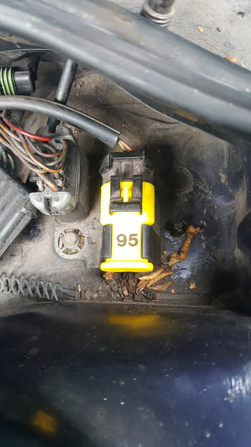
So if you do not have a factory fit anti-theft system, you will have a yellow connector with a blanking cover.
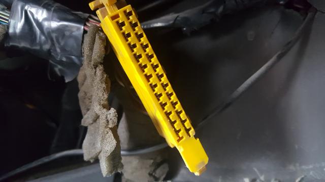
The cover has a metal insert that shorts out the immobiliser pins.

Image

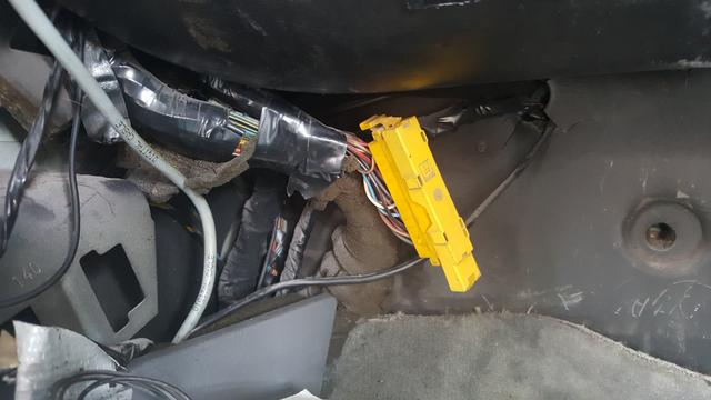
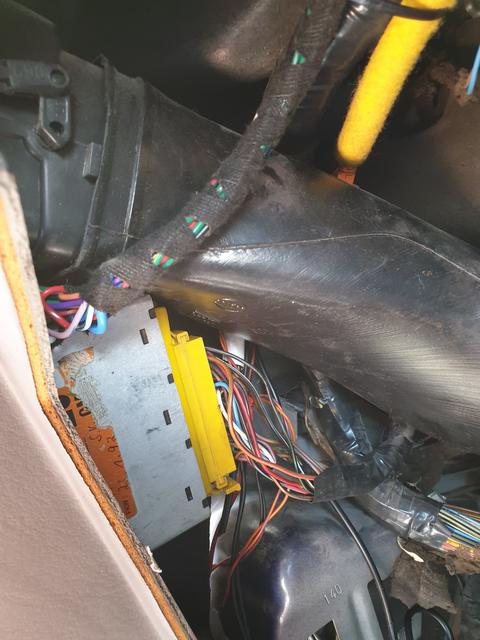
This will be tied up behind the glove box.

Removing the cover reveals the 25 pins inside.

Image

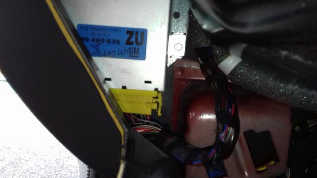
If you do have a factory fit anti theft system, it will be stashed in the left A pillar cavity next to the glove box.

Image

So - what are these pins?.
(This is a table to link my scorpion alarm).

Image

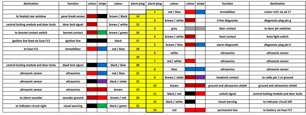
Pin 1 - Blue / Red (or Black / Red) - Fuel Pump Output via the floor loom.
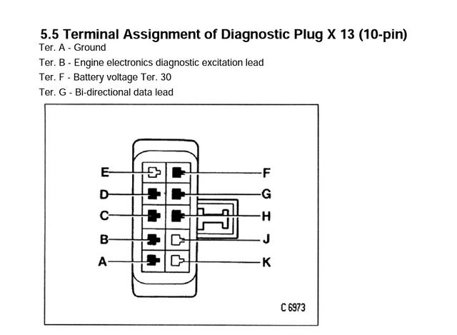
Pin 2 - Brown / White - K Line Diagnostic to diagnostic plug pin G.
Pin 3 - Grey - To door pin switch
Pin 4 - Brown / White - Boot / Hatch Light Switch.
Pin 5 - Brown / Blue - Alarm to Diagnostic Plug pin H.
Pin 6 - white - to ultra sonic unit.
Pin 7 - red / white - to ultrasonic unit.
Pin 8 - blue - to ultrasonic unit
Pin 9 - brown / violet - earthed via radio pin 1
Pin 10 - brown - earth / ground / chassis.
Pin 11 - black / red - central locking unlock signal
Pin 12 - black / white to indicators left.
Pin 13 - red - battery live (no fuse).

Pin 14 - brown / black - Heated Rear Window Element - Pane Break Sensor.
Pin 15 - brown / white - central locking - lock signal
Pin 16 - brown / green - bonnet switch contact.
Pin 17 - black - ignition live (no fuse).
Pin 18 - blue / red - fuel pump fused supply (fuse 11).
Pin 19 - no connection
Pin 20 - black / blue - central locking - dead lock signal.
Pin 21 - red / blue - ultrasonic unit
Pin 22 - black / violet - ultrasonic unit
Pin 23 - brown - ultrasonic unit
Pin 24 - Brown / red - to negative side of Power Sounder (grounded by alarm). And Horn Relay pin 85.
Pin 25 - black / green - to indicators right.

UPDATE - Thread updated as I had the text for pins 4, 11 and 14 wrong, but strangely the table was correct.
User avatar
Robsey
Club Admin
Posts: 10619
Joined: Fri Dec 12, 2008 1:42 pm
Location: East Manchester

Re: Cavalier / Calibra Anti-theft Module Wiring

Post by Robsey »

Voltage Supply Lines.

I have added these to stop you looking for fuses that do not exist.

Pin 13 - Red - Battery / Permanent Live - No fuse / Not Fused.

Pin 17 - Black - Ignition Live - No fuse / Not Fused.

Pin 18 - Red / Blue or Blue / Red - Fuel Pump Feed - Fuse 11

Power Sounder - Red - Battery / Permanent Live - Fuse 38 in the engine bay fuse box. (where fitted).
User avatar
Robsey
Club Admin
Posts: 10619
Joined: Fri Dec 12, 2008 1:42 pm
Location: East Manchester

Re: Cavalier / Calibra Anti-theft Module Diagnostics

Post by Robsey »

DIAGNOSTICS.

This type of Alarm Unit can be connected to a Tech 1 / 1a diagnostic test tool,

Or you can do a flash-code diagnostic by shorting pin A to Pin H of the 10-Pin ALDL plug at the rear left corner of the engine bay.

Here is the ALDL (Assembly Line Diagnostic Link) plug next to my yellow Octane Coding plug.

Image

And here is the Pin-Out for the plug.

Image
---------------------------------------------

ALARM SYSTEM FAULT CODES.

Here is the Alarm Diagnostic Codes list for the factory alarm system, which also includes an immobiliser.

This does not relate to the older Series 90 alarms -
type 901 (door and ignition controlled),
type 902 (with remote control).

I would suspect that other vehicles available at that time could have had the same range of factory alarms fitted either as standard or as an option.  Quite expensive as a retro-fit option.

(Courtesy of Andy Kirwan's Technical site - updated and edited)

Fault codes can be read out of the Alarm by shorting pins A and H in the diagnostic socket.

The inbuilt alarm unit is located at the base of the passenger side A Pillar, hidden behind the glove box.

Image

The code is flashed out on the ultrasonic led in the panel at the top of one of the B Pillars.

The Ultrasonic button clears the codes.

It is written (somewhere) that many Jan 1995 onward Cavaliers and Calibra's will not flash out a fault code.

18 Fault with disarm signal 
25 Horn Voltage Low Horn open-circuit or fuse has blown
26 Indicator Left open circuit
27 Indicator Right open circuit
28 Ultrasonic driver side open circuit or incorrect voltage
29 Ultrasonic passenger side open circuit or incorrect voltage
32 Boot caused an alarm condition
33 Bonnet caused an alarm condition
34 Doors caused an alarm condition
35 Ignition Turned on caused an alarm condition
36 Imbolization circuit open circuit (starter circuit triggered causing alarm)
37 Radio caused an alarm condition
38 Ultrasonic's caused an alarm condition
39 Fault with disarm signal. (central locking fuse blown) (causing alarm condition)
40 Two alarm triggers at the same time.
41 Spare alarm input caused alarm condition (pin 14)
46 Rear Window smashed caused an alarm condition ('92+ models only)
52 Horn Voltage Low Horn Open Circuit or fuse has blown
55 ECU fault
User avatar
vexorg
Registered user
Posts: 417
Joined: Sun Feb 14, 2021 1:22 pm

Re: Cavalier / Calibra Anti-theft Module Wiring

Post by vexorg »

The alarm and immobilser are separate things on the later cars, the immobilser is closely linked to the engine ecu, it needs the right code before the engine will start.

I didn't think the older cars had an immobiliser
David
User avatar
Robsey
Club Admin
Posts: 10619
Joined: Fri Dec 12, 2008 1:42 pm
Location: East Manchester

Re: Cavalier / Calibra Anti-theft Module Wiring

Post by Robsey »

On cars that were not fitted with factory alarm, the retro-fit route was via a System 90 alarm.
(901 and 902 alarms).
I have seen installations where the fitter has connected to the alarm connector, rather than using the "official" scotch lock into the loom above the glovebox method.

The system 90 has an optional 910 fuel pump immobiliser relay that they would connect the 'output' wires to pins 1 and 18 of the alarm connector.

I presume Vauxhall / Opel / GM fitted some looms with various built in options, even if the options were not fitted at the factory.
They always did mix and match their looms to suit their moods or the weather on that day.

Here is a typical alarm unit - pictures from another of my threads.
The main gubbins unclips from the main metal outercasing. Retained by a plastic retainer rivetted to the circuit board.

Image

Image
Post Reply