Cavalier / Calibra Anti-theft Module Wiring
Posted: Wed Mar 30, 2022 2:05 pm
Previously I had not put up the pin-out for the Cavalier for fear that it would allow dodgy site vistors to bypass the immobiliser wires and thus make it easier to steal our pride and joy...
But then I realised that the pin-out is in Haynes anyway, so not so much of a secret after all.
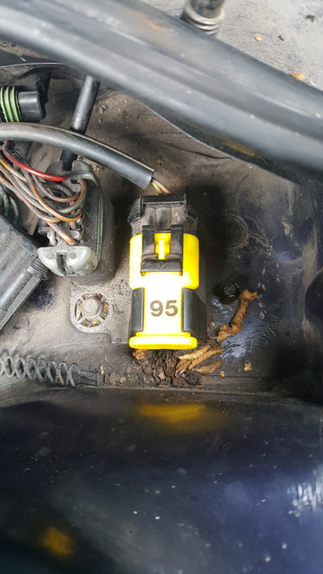
So if you do not have a factory fit anti-theft system, you will have a yellow connector with a blanking cover.
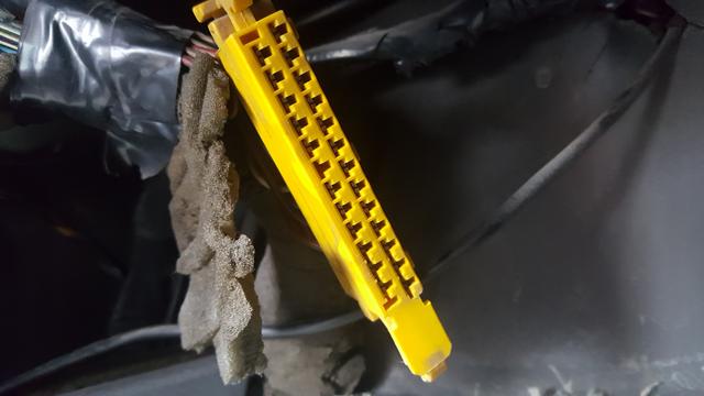
The cover has a metal insert that shorts out the immobiliser pins.
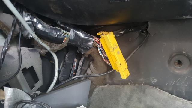
This will be tied up behind the glove box.
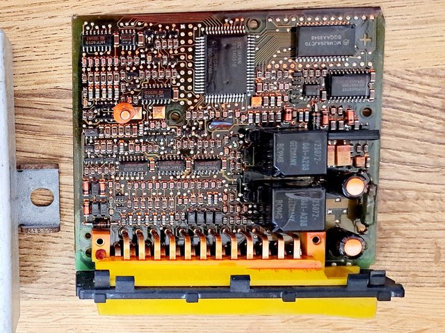
Removing the cover reveals the 25 pins inside.
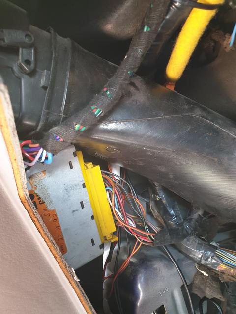
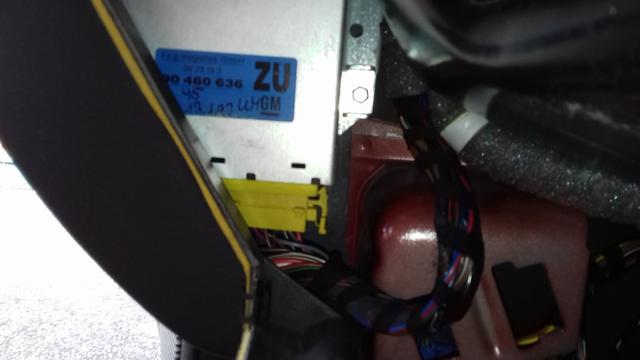
If you do have a factory fit anti theft system, it will be stashed in the left A pillar cavity next to the glove box.
So - what are these pins?.
(This is a table to link my scorpion alarm).
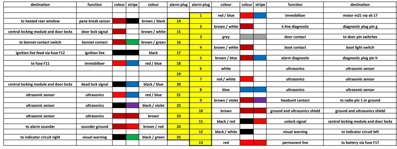
Pin 1 - Blue / Red (or Black / Red) - Fuel Pump Output via the floor loom.
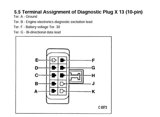
Pin 2 - Brown / White - K Line Diagnostic to diagnostic plug pin G.
Pin 3 - Grey - To door pin switch
Pin 4 - Brown / White - Boot / Hatch Light Switch.
Pin 5 - Brown / Blue - Alarm to Diagnostic Plug pin H.
Pin 6 - white - to ultra sonic unit.
Pin 7 - red / white - to ultrasonic unit.
Pin 8 - blue - to ultrasonic unit
Pin 9 - brown / violet - earthed via radio pin 1
Pin 10 - brown - earth / ground / chassis.
Pin 11 - black / red - central locking unlock signal
Pin 12 - black / white to indicators left.
Pin 13 - red - battery live (no fuse).
Pin 14 - brown / black - Heated Rear Window Element - Pane Break Sensor.
Pin 15 - brown / white - central locking - lock signal
Pin 16 - brown / green - bonnet switch contact.
Pin 17 - black - ignition live (no fuse).
Pin 18 - blue / red - fuel pump fused supply (fuse 11).
Pin 19 - no connection
Pin 20 - black / blue - central locking - dead lock signal.
Pin 21 - red / blue - ultrasonic unit
Pin 22 - black / violet - ultrasonic unit
Pin 23 - brown - ultrasonic unit
Pin 24 - Brown / red - to negative side of Power Sounder (grounded by alarm). And Horn Relay pin 85.
Pin 25 - black / green - to indicators right.
UPDATE - Thread updated as I had the text for pins 4, 11 and 14 wrong, but strangely the table was correct.
But then I realised that the pin-out is in Haynes anyway, so not so much of a secret after all.
So if you do not have a factory fit anti-theft system, you will have a yellow connector with a blanking cover.
The cover has a metal insert that shorts out the immobiliser pins.
This will be tied up behind the glove box.
Removing the cover reveals the 25 pins inside.
If you do have a factory fit anti theft system, it will be stashed in the left A pillar cavity next to the glove box.
So - what are these pins?.
(This is a table to link my scorpion alarm).
Pin 1 - Blue / Red (or Black / Red) - Fuel Pump Output via the floor loom.
Pin 2 - Brown / White - K Line Diagnostic to diagnostic plug pin G.
Pin 3 - Grey - To door pin switch
Pin 4 - Brown / White - Boot / Hatch Light Switch.
Pin 5 - Brown / Blue - Alarm to Diagnostic Plug pin H.
Pin 6 - white - to ultra sonic unit.
Pin 7 - red / white - to ultrasonic unit.
Pin 8 - blue - to ultrasonic unit
Pin 9 - brown / violet - earthed via radio pin 1
Pin 10 - brown - earth / ground / chassis.
Pin 11 - black / red - central locking unlock signal
Pin 12 - black / white to indicators left.
Pin 13 - red - battery live (no fuse).
Pin 14 - brown / black - Heated Rear Window Element - Pane Break Sensor.
Pin 15 - brown / white - central locking - lock signal
Pin 16 - brown / green - bonnet switch contact.
Pin 17 - black - ignition live (no fuse).
Pin 18 - blue / red - fuel pump fused supply (fuse 11).
Pin 19 - no connection
Pin 20 - black / blue - central locking - dead lock signal.
Pin 21 - red / blue - ultrasonic unit
Pin 22 - black / violet - ultrasonic unit
Pin 23 - brown - ultrasonic unit
Pin 24 - Brown / red - to negative side of Power Sounder (grounded by alarm). And Horn Relay pin 85.
Pin 25 - black / green - to indicators right.
UPDATE - Thread updated as I had the text for pins 4, 11 and 14 wrong, but strangely the table was correct.