
IT DOES NOT HAVE ANY ALARM OR IMMOBILISER FUNCTIONS.
Taken as an abstract from the man discussion thread found here.
viewtopic.php?f=15&t=16228
And then updated as information is gathered and improved.
FITTING A KIEKERT VECTRA-B CENTRAL LOCKING MODULE.
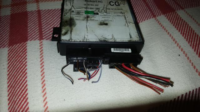
PART NUMBER - 90 564 349
ALPHA CODE - CG.
Parts needed are: -
ALL Vectra-B remote central locking units have two sockets.
A 12 Pin connector that matches the connector from the Cavalier loom.
The second socket has 28 pins in it.
For Basic Remote Central Locking.
(Lock and unlock)
Only the 12 pin socket is needed.
1 - Kiekert module - part number 90 564 349. Mine has alpha code CG on it.
2 - A Vectra-B key fob.
Ensure that the key fob is synchronised to the locking module
And that is it.
Just plug it in and away you go.
---------------------------------------
For additional "lighting" options you need to use the 28 pin connector as detailed below: -
INTERIOR LIGHT ILLUMINATION
28 Pin Connector Pins 11 and 15.
The interior light illuminates for few seconds when the unlock button is pressed, or immediately after the last door is closed.
UPDATED.
Look behind the door dip switch on the driver's door frame.
Your door dip switch has two male spade connections.
One has a single Grey / White wire to the lights on warning buzzer- connected via a female spade.
And multiple grey wires on the other male spade for the various door open functions including interior light control.
My suggestion is to daisy chain the central locking module between the door dip switch and the interior light.
1 - Fit a black / grey wire to pin 11 and fit a male spade at the end.
The wire should be long enough to reach comfortably from the module to the door dip switch.
2 - Fit a grey / white wire to pin 15 and fit a female spade connector at the end.
Again the wire should be long enough to reach comfortably from the module to the door dip switch.
3 - Unplug the grey / white connector already plugged into the dip switch, and connect this to the black / grey wire from pin 11.
4 - Fit another grey wire to pin 16, long enough to reach comfortably from the module to the door dip switch.
This wire needs to be wired as a "T" at the dip-switch end, with a male spade on one arm and a female spade on the other
5 - Disconnect the connector with multiple grey wires that meet, at the dip switch.
6 - Connect the "T" end of the grey wire from pin 16 between the bunch of grey wires on one arm (male spade) and the dip switch itself on the other arm (female spade).
Ensure that no metal connectors can short to each other or the door frame. - to avoid false interior light or locking issues.
-----------‐------------------------------------------
The result is that when you unlock the doors via the fob, or after you close the door, the interior light will remain illuminated for a couple of seconds.
-------------------------------------------------------
FLASHING THE INDICATORS ON LOCK OR UNLOCK BUTTON PRESS.
28 Pin Connector Pin 14.
This flashes the indicators once for about 1/2 a second on the press of a fob button.
This is best achieved using a 5 pin relay.
The relay pins are as follows:-
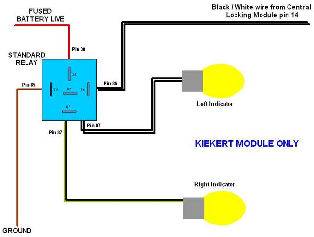
Pin 30 is battery voltage - Run to a permanent live supply. Remember to insert a fuse into this wire.
Pin 85 is the ground wire - Run a wire to a metal earthing point. You could use the hole that the self-tapping screw goes into to secure the central locking module.
Pin 86 is the control wire - This goes to Central Locking Module pin 14 of the 28 pin connector.
Pin 87 (There are two pin 87s) - Connect a wire from each of the "87" legs to each of the indicator wires.
Left is Black / White, and Right is Black / Green.
(Ensure that the "87" pins are not joined within the relay, when the relay is "off".
Plug in together and check your handy-work.
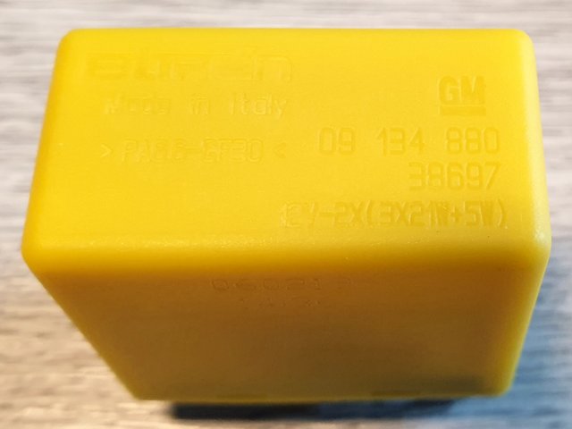
Alternatively you could use the proper Vectra / Omega Yellow Relay - as follows.
Kiekert is switched live (12volt trigger).
Gives a brief 12 volt pulse when you press the lock and / or unlock buttons.
Yellow GM Flasher Relay.
Part number 9134880.
Approx £18 from GPS for GM part, or £21 for an OEM part.

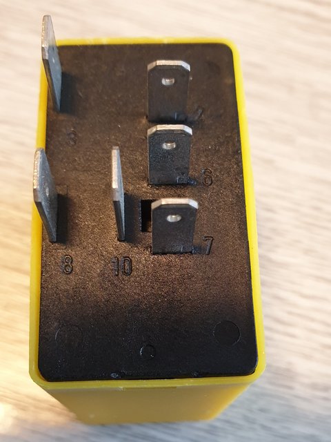
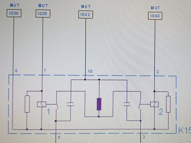
Connecting Up.
Pins 2 and 7
The two smaller pins for Flash control trigger wire. (12 volt pulse).
These should be connected to the black / white wire from the anti-theft connector pin 14 (28 pin plug).
This relay is independent of the indicator and hazard flasher unit on the Cavalier.
Pins 3 and 8
are outputs to the indicators.
Pin 3
black / green (right) to cavalier alarm plug pin 25,
Pin 8
black / white (left) to cavalier alarm plug pin 12.
Pin 6
Brown wire becomes your relay 'common' ground connection.
If you are attempting this install, I shouldn't need to tell you how to wire a ground / chassis / earth wire.
Pin 10.
The bigger pin with red feed wire should be connected to battery live.
You can connect this to cavalier alarm connector pin 13.
--------------------------------------------------------