
Comments and questions about this How 2 can be posted in the linked thread below.
viewtopic.php?f=15&t=16488&p=166602#p166602
Saloon models.
If you have a boot, then adding the 3rd brake light is a piece of cake, and so if you need a guide for that, you should perhaps look at getting someone else to do it.
See Post #2 for where to wire up to.
So this thread will concentrate on the Hatchback models.
There is an easy, tacky way,
a not so easy, but proper way,
and a damned near impossible way to fit the wiring for a third brake light to your Cavalier.
The easy way
is to run a wire loosely from the nearside rear inner wing, up the d pillar, under the plastic trims of your hatch to the brake light that is mounted centrally above the bottom edge of the tailgate glass.
But this means the feed wire is not buried within the loomage and rubber sleeve as it should be.
So looks unprofessional and leaves the cable at risk to flexing and eventually snapping when you open and close the hatch.
The "damned near impossible" way
is to try and feed a wire through the hatch frame following the existing loom.
Trust me, I tried doing this several times to avoid ripping out the tailgate harness.
But in my opinion, it cannot be done.
So - here is the only proper way to add the wiring.
Warning it is long, slow and tedious, due to the amount of dismantling and refitting of trims,
Plus the hassle of pulling out, modifying and refitting of the tailgate loom.
How 2 - Fit a 3rd Brake Light.
Moderator: Robsey
Re: How 2 - Fit a 3rd Brake Light.
Firstly the wiring diagram..
If you Do Not have Check Control -
It is two wires, so no diagram needed.
Wire 1 -
Brake light feed wire.
Officially a black wire with yellow stripe.
If you have the official GM retrofit kit, both supply and return wires are black.
If you are fortunate enough to have a trailer loom connector just inside the load area - approx mid-way across, inside the rear panel, covered by the plastic boot trim, then you do not need to 'splice' into the wiring. Just crimp / solder on a suitable connector pin and plug it in.
You simply connect to the black wire with yellow stripe in the X45 connector.
For everyone else, you will need to splice into a black wire with yellow stripe from either one of your rear light clusters.
Wire 2 -
The earth return / chassis wire.
This simply needs to be connected to any earth tag in the tailgate. There are at least two of these earth tag points on most vehicles.
If you have "Check Control", you will need to add a relay to prevent false warning lights on the instrument panel.
I don't have check control on my car, but there is a series of "pictogram" instructions on the next post for those that do.
Re: How 2 - Fit a 3rd Brake Light.
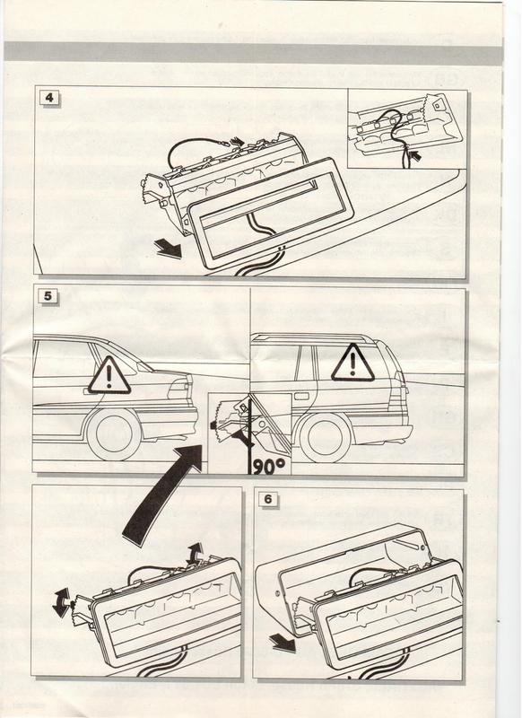
Here are the official GM instruction notes.
Part number for this kit is 90513225
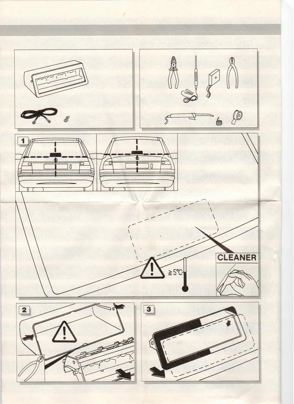
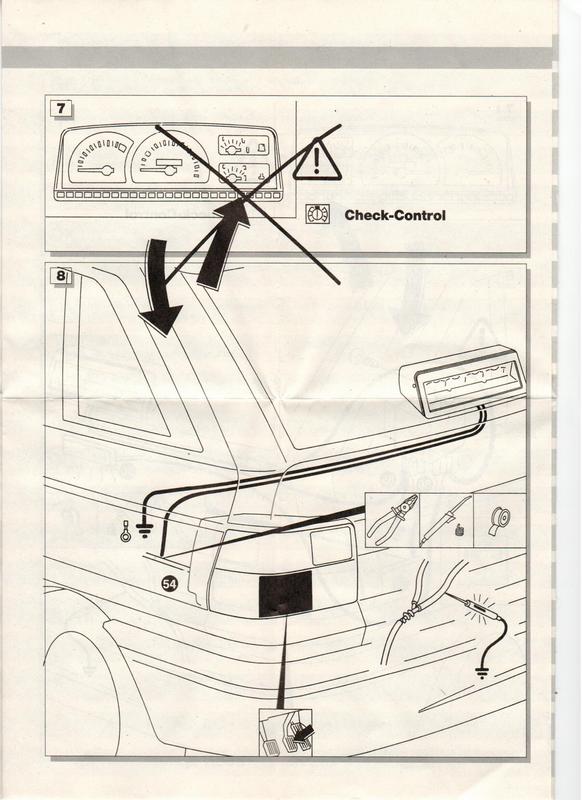
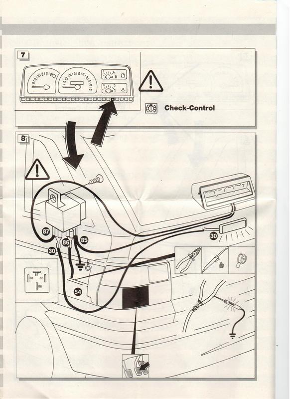
Standard Notation for the numbers on the Pictograms - and on wiring diagrams / Schematic drawings.
15 = Ignition live voltage. Usually a black wire on Cavaliers.
30 = Permanent battery live. Usually a red wire on Cavaliers.
30 is also used to identify the pin of a relay that is connected to the supplying voltage that will be used to power the light unit (or other accessory).
54 = The black wire with yellow stripe for the rear light cluster brake light.
85 = The ground terminal of a relay. The ground for the control circuit of the relay.
The symbol of three lines in a triangle also represents a ground or chassis connection.
A ground wire is usually brown in a Cavalier and such ground wires may be identified with the number 31 on circuit diagrams.
86 = The control circuit input voltage of a relay. The voltage used to trigger the relay.
87 = The output voltage from the relay to the light or other accessory that is controlled by the relay. The item wired to terminal 87 is often termed as " the Load".
Part number for this kit is 90513225
Standard Notation for the numbers on the Pictograms - and on wiring diagrams / Schematic drawings.
15 = Ignition live voltage. Usually a black wire on Cavaliers.
30 = Permanent battery live. Usually a red wire on Cavaliers.
30 is also used to identify the pin of a relay that is connected to the supplying voltage that will be used to power the light unit (or other accessory).
54 = The black wire with yellow stripe for the rear light cluster brake light.
85 = The ground terminal of a relay. The ground for the control circuit of the relay.
The symbol of three lines in a triangle also represents a ground or chassis connection.
A ground wire is usually brown in a Cavalier and such ground wires may be identified with the number 31 on circuit diagrams.
86 = The control circuit input voltage of a relay. The voltage used to trigger the relay.
87 = The output voltage from the relay to the light or other accessory that is controlled by the relay. The item wired to terminal 87 is often termed as " the Load".
Re: How 2 - Fit a 3rd Brake Light.
The first thing to do is open the rear hatch / tail-gate.
Undo the torx screws holding the hatch internal cover to the tail-gate.
The screws are undone with a torx T25 screwdriver or torx profiled allen key type tool.
I had to undo one screw from the off side hatch trim.
And remove all the torx screws, the parcel-shelf strap-hanger bobbin and the plastic trim panel from the nearside hatch frame.
This now exposes where the heated rear window demister connection is.
This is a snug fitting female spade connector.
Carefully un-plug this and tape a strong thin chord or wire to the plug.
I had to press my courtesy light switch pin in to allow the trim panel to fall away from the tail-gate.
You will now be able to see all the tail-gate interior.
There are three connectors to unplug.
1 - for the wiper motor
2 - for the hatch central locking
3 - a female spade connector for the courtesy light switch (it may be easier to undo the No2 philips screw to allow you to get at the connector. I refitted my switch to save losing it.
There is at least one earth tag screwed to the panel, again using a No2 philips screw.
Tape a piece of strong thin chord or wire to one of the main plugs on the loom.
Now that all the plugs etc are disconnected, it will be possible to pull the loom out of the hatch.
Pull the elephant's trunk / corrugated rubber hose from the top of the tail-gate.
Then gently ease the loom out of the hatch frame. A combination of pulling from the hole where the cable leaves the hatch, and pushing the loom gently on it's way up the side of the hatch frame.
Note that the heated rear window connector has to be fed through a 1/2" (13mm) approx hole before it can be drawn out.
The two chords that you attached will need to be long enough to follow the routes taken by the loom on it's removal.
Then tied in place ready for refitting later.
That is the hatch part done.
Now for the rear inner wing.
Re: How 2 - Fit a 3rd Brake Light.
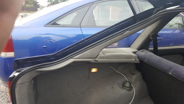
First clear the load area enough to give full access to the nearside cover panel and the rear plastic panel.
This bit is optional to gain better access to the inner wing cavity.
But it does not affect getting the loom out of or into the wing.
It goes without saying that you need to undo the many T25 torx screws that hold the speaker shelf / rear quarter / 'D' pillar covering trim.
Also peel away the rear hatch rubber seal from the nearside hinge, all down the near side, and down across the bottom of the hatch lip.
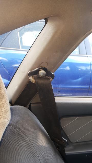
To remove the rear quarter plastic surround you will also need a 21mm spanner or socket to remove the upper seat belt mount. Access by popping off the plastic cap.
Don't forget to unplug your rear speaker!!
* * *
Pull away the nearside light cluster cover and remove the nearside inner wing cover.
Now that all the trims are off, you will need to unplug two connectors.
1 - round connector for the heated rear window and courtesy light.
2 - a small square plug for the central locking.
Plus one small earth tag held onto the wing by a No2 philips self tapping screw.
Again for improved access to the cavity, you may wish to remove the aerial.
(Electric aerials obviously have an extra electrical connector to disconnect).
* * *
Time to remove the loom.
Pull the flange of the corrugated rubber hose from the d pillar.
Carefully ease the loom up the d pillar, whilst drawing out the loom through the big hole.
You will find that the sunroof rear drain hose also runs down the d pillar, so you will need to ease the hose gently to one side whilst you pull the plugs out through the hole.
That is it.
The whole loom is now out.
Now is a good time to look for damage to the insulation or snapped wires.
I had to repair six of the ten wires in my loom and add the wire for the 3rd brake light.
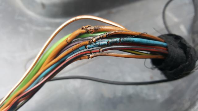
I unwrapped most of my pvc looming tape before adding the brake light wire
If you are being pedantic, you should use a black wire with a yellow stripe.
But it is up to you -
You could used one of the black twin cores from the brake light kit, or a wire of your colour choice, as long as it is of a decent thickness for the job.
0.75mm or similar should do the trick.
Then I re-wrapped / loomed up the whole cable with Tesa fabric looming tape.
This bit is optional to gain better access to the inner wing cavity.
But it does not affect getting the loom out of or into the wing.
It goes without saying that you need to undo the many T25 torx screws that hold the speaker shelf / rear quarter / 'D' pillar covering trim.
Also peel away the rear hatch rubber seal from the nearside hinge, all down the near side, and down across the bottom of the hatch lip.
To remove the rear quarter plastic surround you will also need a 21mm spanner or socket to remove the upper seat belt mount. Access by popping off the plastic cap.
Don't forget to unplug your rear speaker!!
* * *
Pull away the nearside light cluster cover and remove the nearside inner wing cover.
Now that all the trims are off, you will need to unplug two connectors.
1 - round connector for the heated rear window and courtesy light.
2 - a small square plug for the central locking.
Plus one small earth tag held onto the wing by a No2 philips self tapping screw.
Again for improved access to the cavity, you may wish to remove the aerial.
(Electric aerials obviously have an extra electrical connector to disconnect).
* * *
Time to remove the loom.
Pull the flange of the corrugated rubber hose from the d pillar.
Carefully ease the loom up the d pillar, whilst drawing out the loom through the big hole.
You will find that the sunroof rear drain hose also runs down the d pillar, so you will need to ease the hose gently to one side whilst you pull the plugs out through the hole.
That is it.
The whole loom is now out.
Now is a good time to look for damage to the insulation or snapped wires.
I had to repair six of the ten wires in my loom and add the wire for the 3rd brake light.
I unwrapped most of my pvc looming tape before adding the brake light wire
If you are being pedantic, you should use a black wire with a yellow stripe.
But it is up to you -
You could used one of the black twin cores from the brake light kit, or a wire of your colour choice, as long as it is of a decent thickness for the job.
0.75mm or similar should do the trick.
Then I re-wrapped / loomed up the whole cable with Tesa fabric looming tape.
Re: How 2 - Fit a 3rd Brake Light.
Next phase is to refit the whole loom back into the d pillar and into the hatch using a reversal of the process for getting the loom out.
General gist is...
Tie or tape the draw chords to the two tail-gate connectors that you attached to before.
Be sure the draw chords are secure.
Then pull the chords carefully to draw the wires back into place.
The heated rear window plug will need teasing through the 1/2" access hole.
Once the hatch wires are pulled through, connect everything back up.
Cable tie / Zip tie your cable runs to the hatch to minimise vibration rattles.
Do the same procedure for the d pillar section of the loom.
Again - reconnect the plugs and secure everything in place.
That just leaves connecting up the feed wire.
Remove the rear plastic cover to see if you have the X45 connector, just above the centre line of the rear bumper.
I don't have this plug, so will have to link into one of the rear light clusters.
When that is all done, refit all your trims, seat belt upper mount and the hatch frame rubber seal.
Re: How 2 - Fit a 3rd Brake Light.
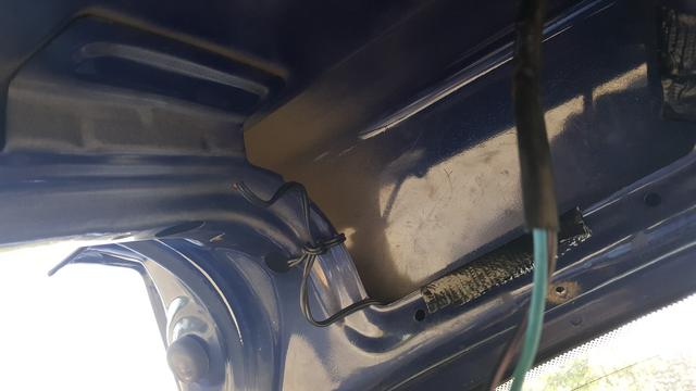
The Hatch Connections.
Central Locking Connector (Hatch Solenoid motor).
With freshly wrapped loomage - nice.
The connector for the Rear Window Wiper Motor.
Central Locking Connector (Hatch Solenoid motor).
With freshly wrapped loomage - nice.
The connector for the Rear Window Wiper Motor.
Re: How 2 - Fit a 3rd Brake Light.
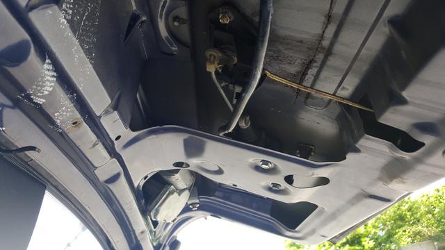
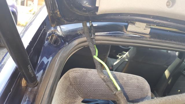
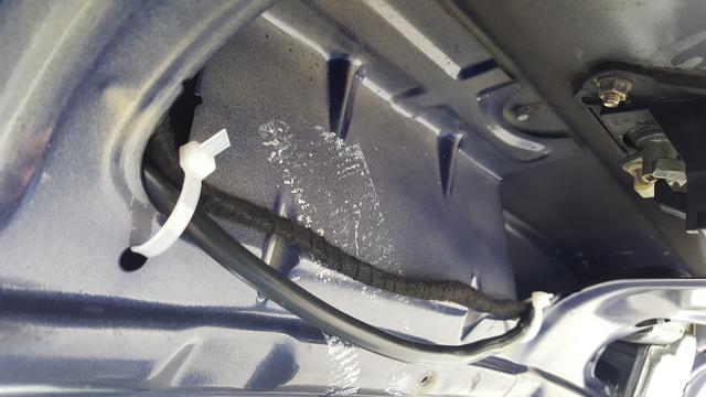
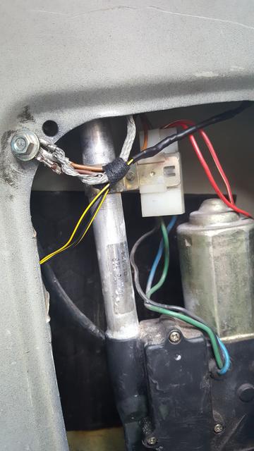
Inner Wing Connections.
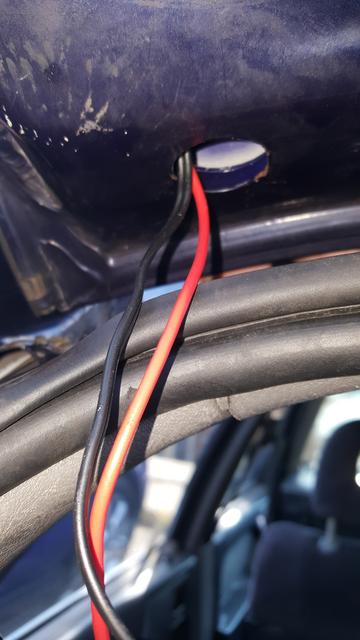
Thread the loom down the D pillar.
Turns out that there is a hidden lip or something at the bottom of the channel within the pillar.
Not easy manipulating the loom over the lip, out of the bottom of the channel.
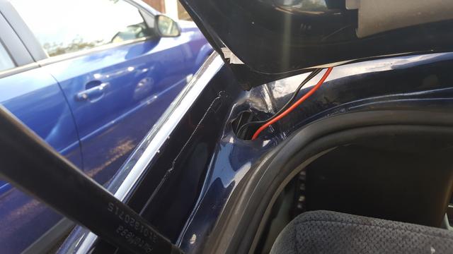
It is hidden high up inside the inner wing.
I had to pull out the electric aerial so that I had enough space to get my hand into the void above it and push the sun-roof drain tube out of the way with two fingers whilst I guided the loom through with my thumb and little finger.
Eventually after a lot of cursing and scratches to my arms, I was able to continue pulling the loom down until I could connect the plugs to the main body loom.
Thread the loom down the D pillar.
Turns out that there is a hidden lip or something at the bottom of the channel within the pillar.
Not easy manipulating the loom over the lip, out of the bottom of the channel.
It is hidden high up inside the inner wing.
I had to pull out the electric aerial so that I had enough space to get my hand into the void above it and push the sun-roof drain tube out of the way with two fingers whilst I guided the loom through with my thumb and little finger.
Eventually after a lot of cursing and scratches to my arms, I was able to continue pulling the loom down until I could connect the plugs to the main body loom.
Re: How 2 - Fit a 3rd Brake Light.
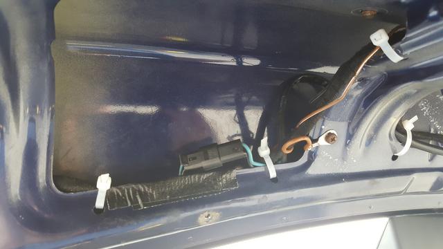
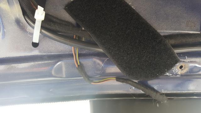
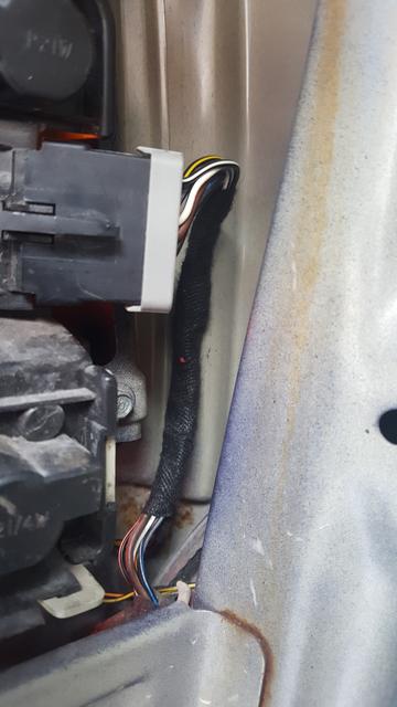
Wires reloomed and connected.
The wiring for the brake light tidied and loomed up to the main loom.
The Velcro wool gives good protection from vibration and sharp panel edges.
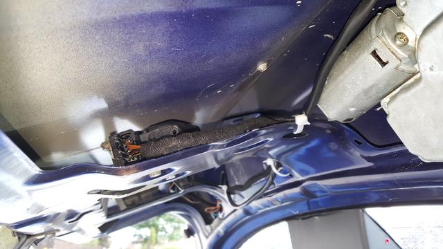
The two main connectors in the wing.
The square green connector and
the black barrel shaped connector.
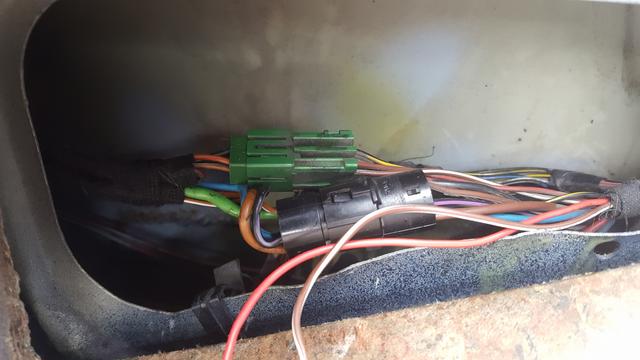
The wiring to the tail light cluster.
You can see two black wires with yellow stripes, because I wasn't sure if a single wire was enough cross section area for the current consumed by the 3rd brake light unit. So I doubled up the wires just to be sure. As it happens, it is from where the loom emerges in the rear quarter to the tail light cluster.
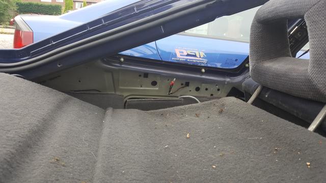
Interior refitted.
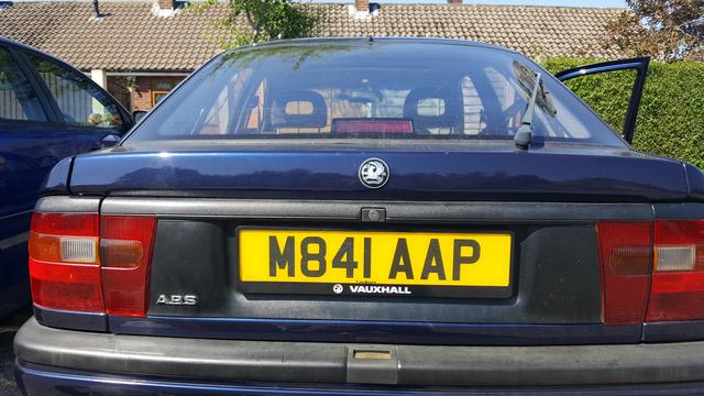
And here you go.
Brake off
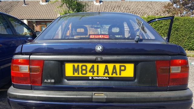
Brake on.
There is a scale on the red plastic lense / bulb holder assembly.
This allows you to set the bulbs and reflector to the preferred angle.
The instruction sheet says set the angle gauge so that the bulbs are pointing horizontally (parallel to the ground).
The wiring for the brake light tidied and loomed up to the main loom.
The Velcro wool gives good protection from vibration and sharp panel edges.
The two main connectors in the wing.
The square green connector and
the black barrel shaped connector.
The wiring to the tail light cluster.
You can see two black wires with yellow stripes, because I wasn't sure if a single wire was enough cross section area for the current consumed by the 3rd brake light unit. So I doubled up the wires just to be sure. As it happens, it is from where the loom emerges in the rear quarter to the tail light cluster.
Interior refitted.
And here you go.
Brake off
Brake on.
There is a scale on the red plastic lense / bulb holder assembly.
This allows you to set the bulbs and reflector to the preferred angle.
The instruction sheet says set the angle gauge so that the bulbs are pointing horizontally (parallel to the ground).