Diagnostic Mode d:5
NOTE - Where the "Universal / Diagnostic Switch" is mentioned, it is equivalent to shorting pins A and D of the diagnostic socket together.
When program memory is replaced, the range indicator must be recalibrated, in case of inexact indication the range must be corrected.
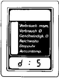
To do this, select diagnostic mode 5.
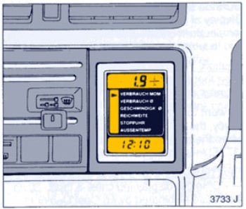
The clock display shows "d : 5".
The function display at first remains blank.
Further procedures for range recalibration or correction are described below.
Adjustments
Range Calibration
Recalibration of the range indicator is necessary after replacing:
- board computer
- program memory
- fuel gauge
- voltage stabilizer
- LCD instrument
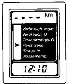
If "---- km (m)" appears continuously in function display when the range indicator function is selected, the board computer must be re-initialized by disconnecting the battery > 2 min.
Requirements for recalibrating the range are:
- board computer functions correctly
- correct program memory is installed
- fuel gauge in instrument is in order
The Universal Potentiometer KM-644-1 is required for recalibration.
Adjustment and connection are to be carried out as follows:
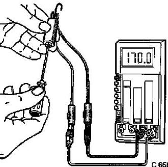
- Connect Multimeter MKM-587-A to universal potentiometer (measuring range 200 ohms).
- Loosen clamping nut at universal potentiometer and adjust potentiometer with screwdriver to nominal value.
- Retighten clamping nut.
- Disconnect measurement lead (round plug) and ground lead (flat plug) at fuel tank gauge.
- Connect universal potentiometer to both leads.
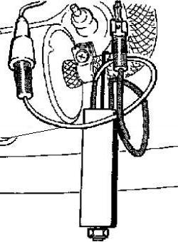
The tank gauge is not connected during the calibration!
Notes:
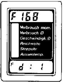
• The universal potentiometer should be connected prior to TECH 1, with ignition switched off.
Otherwise, the board computer self-diagnosis recognizes Fault No. 168 after tank gauge is disconnected.
potentiometer and reconnecting the tank gauge.
• If tank gauge is sealed, Adapter KM-644-2 is required for connecting Potentiometer KM-644-1.
With TECH 1
Adjust Universal Potentiometer KM-644-1 to substitutional resistance and connect instead of the tank gauge (ignition OFF!).
Connect TECH 1, check program memory code and if necessary eliminate present stored faults.
Actuation of key F6 then F0 changes TECH 1 to the calibration mode.
Acknowledge the following TECH 1 displays with YES.
If calibration is correct, TECH 1 returns to mode F6: Adjustments, which is exited by EXIT.
Disconnect universal potentiometer and connect tank gauge (ignition OFF!).
With Diagnostic Switch KM-640
Adjust Universal Potentiometer KM-644-1 to substitutional resistance and connect instead of the tank gauge (ignition OFF!).
Connect Diagnostic Switch KM-640.
Adjust diagnostic mode 5 by repeatedly actuating the stepping key.
The clock display shows "d : 5".
The function display remains blank.
Change is made to the actual calibration mode by pressing the minutes hole contact.
The clock display shows "A".
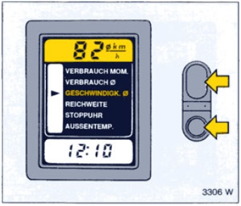
The function selection display flashes the range arrow.
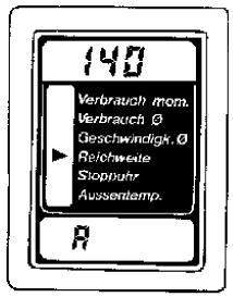
The function display shows "12 l" (calibration with defined petrol quantity). This calibration mode is used only in the factory.
A switchover is made to the calibration mode with substitutional resistance by pressing the stepping key.
The function display shows the value of substitutional resistance.
Adjust Universal Potentiometer KM-644-1 to substitutional resistance and connect instead of the tank gauge.
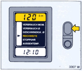
The calibration process is initiated after the start key until storage is ended.
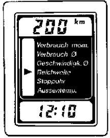
After approx. 5 sec, the function display shows the range corresponding to the substitutional resistance (approx. 120 km or 75 m).
The calibration mode is exited by disconnecting the diagnostic switch.
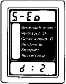
If during calibration the board computer recognizes a faulty signal level, an "H" (voltage too high) or "L" (voltage too low) flashes for 5 sec instead of the range being displayed.
The board computer then returns to diagnostic mode 5.
In this case, check adjustment of universal potentiometer or the board computer periphery (see section 6).
After a successful recalibration, the following measures are to be carried out:
- Remove universal potentiometer, connect tank gauge (ignition OFF!)
- Erase trouble code memory.
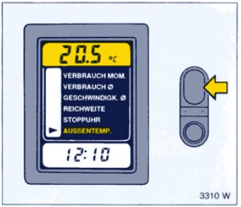
- Select board computer range function and press start key. The function display shows the range calculated from the current tank content.
Range Correction
This possibility of calibration enables differences between the range indicated by the board computer and the actual range of the vehicle to be corrected. This condition can arise, for example, after the board computer is replaced.
Correction of tank content is possible in a range of ± 3 l (± 1.2 gal) in 0.5 l (0.2 gal) stages.
Important:
Carry out a correction of the tank content only if differences between the range indicated by the board computer and the actual range have occured for a considerable period of time and with the same order of magnitude.
For safety reasons, the range indicator has been so designed that when the board computer display reads 0 km, a distance of approx. 5 to 10 km (3 to 6 m) can still be traversed. This safety reserve must not be decreased by a correction of the tank content.
In case of larger deviations, the range indicator should be recalibrated.
The following equivalences serve as recommended values for converting between tank content and range:
0.51 » 5 km (0.2 gal. » 3 miles).
With TECH 1
Connect TECH 1, check program memory code and eliminate faults which may be present.
Actuation of key F6 then F1 changes TECH 1 to the range correction mode. The TECH 1 Display shows:
SELECT VALUE
VOLUME
xx km
(ENTER)
Input of the desired correction value can be made using the + and ¯ keys and confirmed with the ENTER key.
If correction is made without error, TECH 1 returns to the mode F6: Adjustments, which is exited by EXIT.
To check range correction: see Test Step 02 in Data List F0.
With Diagnostic Switch KM-640
Connect Diagnostic Switch KM-640.
Adjust diagnostic mode 5 by repeatedly actuating stepping key.
The clock display shows "d : 5".
The function display remains blank.
Change is made to the actual correction mode by pressing the hours hole contact.
The clock display shows "A: xx"; at the same time,the currently stored correction appears at the positions designated by xx.
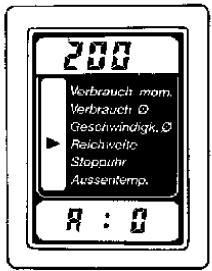
The correction value is displayed without a decimal point, e.g. 15 for 1.5 l (6 for 0.6 gal).
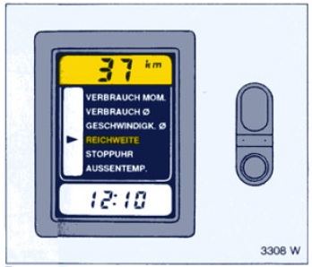
The function selection display flashes the range arrow.
The function display shows the range based on the current tank content, a standard consumption of 10 l/100 km (28.3 m/gal) and the currently adjusted correction.
The stepping key can be used to adjust the desired correction in the clock display in the continuous mode.
Simultaneously, the displayed range changes by approx. 5 km (3 m) with each key actuation.
If the right correction value has been set, the correction value is permanently stored in the program function display shows "----" until storage is ended.
The correction mode is exited by disconnecting the diagnostic switch.
Then: select board computer range function and press start key. The function display shows the range calculated from current tank content.
Examples
Example 1
Customer complaint: With a range indication of 17 km (11 m) in the board computer display, the engine stopped because of insufficient fuel.
Action: Adjust the next higher value as a negative quantity by means of range correction; here - 20 km (- 12 m).
The board computer now shows a range that is smaller by 20 km (12 m).
Example 2
Customer complaint: With a range indication of 0 km (0 m), 32 km (20 m) can still be driven. A deviation of this order of magnitude could be observed over a considerable period of time.
Action: So as not to fall below the safety reserve, adjust to the next but one smaller value; here 25 km (15 m).
The board computer now shows a range that is greater by 25 km (15 m).
Example 3
Customer complaint: Over a considerable period of time, the range indication is observed to deviate by more than ± 40 km (± 25 m) from the actual value.
Action: Recalibrate the range indicator.
Time Adjustment
An adjustment of the clock is necessary,
- if the current supply at the board computer was interrupted for longer than 3 seconds;
- for converting between summer and winter time or during long distance travel;
- at irregular intervals to equalize precision.
With TECH 1
Connect TECH 1, check program memory code and eliminate faults which may be present.
Actuation of key F6 then F2 changes TECH 1 to the time mode. The TECH 1 display shows:
SET TIME
hh:mm:ss
(ENTER)
The hours position hh flashes and can be changed by means of the and ¯ keys, and transferred to the board computer by using the ENTER key Adjustment of minutes (mm) and seconds (ss) then occurs analogously.
After the seconds position is adjusted, TECH 1 returns to the mode F6: Adjustments, which is exited by EXIT.
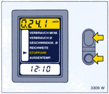
With Control Unit
By actuating the hole contacts, the hours and minutes positions of the board computer display can be adjusted in the continuous mode and started to the exact second with the start or stepping key.