This is an abstract taken from the discussion thread found here.
viewtopic.php?f=15&t=16228
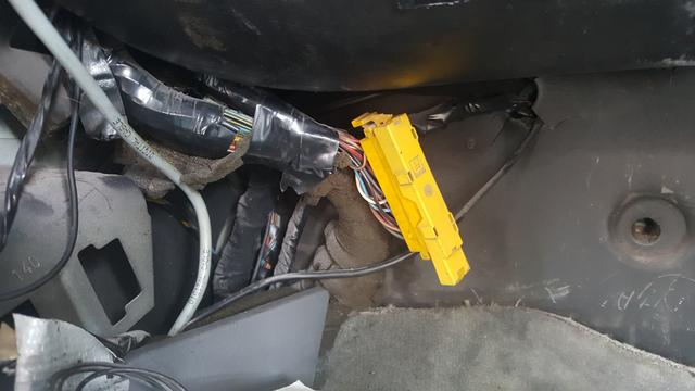
FITTING THE MEGAMOS UNIT AS A CENTRAL LOCKING MODULE.
ALL Vectra-B remote central locking units have two sockets.
A 12 Pin connector that matches the connector from the Cavalier loom.
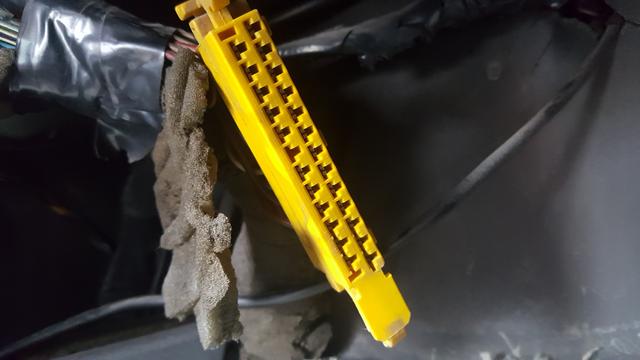
The second socket has 28 pins in it.
Even in it's most basic format, this module must have a 12 volt supply applied to pin 18 of the 28 pin connector.
Without this, it will never work.
Parts required are therefore: -
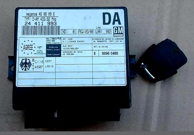
1 - Megamos Central Locking Unit.
PART NUMBER is - 24 411 993
ALPHA CODE is - DA
2 - 28 Pin Connector and a length of wiring.
3 - Remote Key fob
Ensure that the key is synchronised to the module.
4 - To flash the indicators, you will need a Vectra-B relay
--------------------------------------------------------
"Additional Options and ATWS".
All options are wired to the 28 pin socket, as follows:-
Pin 10 - DEAD LOCKING.
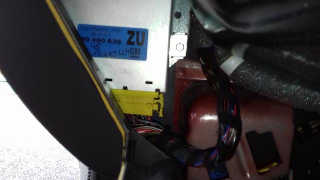
The black / blue wire for dead-locking on pin 10 of the 28 pin plug, should be connected to pin 20 of the yellow alarm connector (up behind the glove-box).
--------------------------------------------------------
Pin 11 - INTERIOR LIGHT WITH DELAY
Look behind the door dip switch on the driver's door frame.
Your door dip switch has two male spade connections.
One has a single Grey / White wire to the lights on warning buzzer- connected via a female spade.
And multiple grey wires on the other male spade for the various door open functions including interior light control.
My suggestion is to daisy chain the central locking module between the door dip switch and the interior light.
1 - Fit a black / grey wire to pin 11 and fit a male spade at the end.
The wire should be long enough to reach comfortably from the module to the door dip switch.
2 - Fit a grey / white wire to pin 15 and fit a female spade connector at the end.
Again the wire should be long enough to reach comfortably from the module to the door dip switch.
3 - Unplug the grey / white connector already plugged into the dip switch, and connect this to the black / grey wire from pin 11.
4 - Connect Grey / white wire from Pin 15 to the male spade on the dip-switch that you have just removed the original wire from.
Ensure that no metal connectors can short to each other or the door frame. - to avoid false interior light or locking issues.
-----------‐------------------------------------------
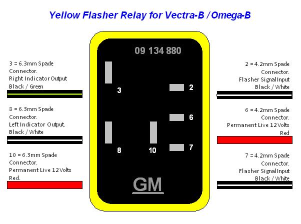
14 - Output to Flash the Indicators.
Gives a brief pulse to ground when you press the lock and / or unlock buttons.
UPDATE - TESTED ON 12/11/22 AND THE TRIGGER SIGNAL IS TO GROUND BUT POLARITY ACROSS THE RELAY PINS ARE REVERSED COMPARED TO MY WORKTOP TESTS.
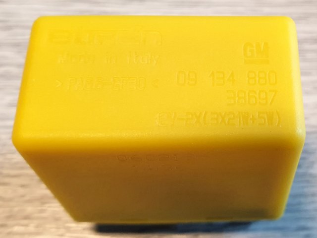
For flashing the indicators when arming and disarming the anti-theft module I have discovered that the Vectra-B uses a specific yellow relay.
Part number 9134880.
Approx £18 from GPS for GM part, or £21 for an OEM part.
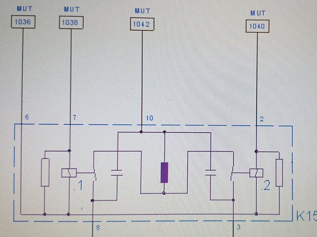
I have looked into how it "should" work.
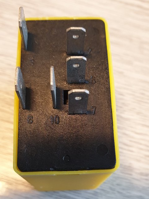
Two red feed wires should be connected to battery live. (Relay pins 6 and 10).
This relay is independent of the indicator and hazard flasher unit on the Cavalier.
You can connect them all to cavalier alarm connector pin 13 - red wire.
UPDATE - RED WIRES GO TO PINS 6 AND 10.
Pins 2 and 7
black / white wire to the anti-theft connector pin 14 (28 pin plug).
Flash control trigger wire.
UPDATE - SPLIT THE BLACK / WHITE FROM THE ATWS MODULE AND CONNECT TO PINS 2 AND 7.
Pins 3 and 8 are outputs to the indicators.
Pin 3
black / green (right) to cavalier alarm plug pin 25,
Pin 8
black / white (left) to cavalier alarm plug pin 12.
--------------------------------------------------------
15 - Driver's Door Pin Switch.
Please see Pin 11 - Interior light triggering.
---------------------------------------------------------
16 - Passenger Door Pin Switches.
Pin 16 is the trigger wire for all three passenger doors.
Fit a grey / white wire from pin 16 of the ATWS unit and connect this to the front passenger door dip switch.
-------------------------------------------------------
17 - Boot Load Area light switch. - (ATWS)
Triggers the alarm when the hatch / boot is opened. (when the wire is shorted to ground).
Connect to wire for boot light, between the bulb holder and the switch.
Or to the alarm connector pin 4.
A brown / white wire.
Check that the boot switch wire IS connected to the alarm connector.
It is not on my 1994 LSi.
Therefore I had to run a wire from the hatch light switch to the rear passenger door dip switch and use pin 16 instead of pin 17 of the ATWS unit.
--------------------------------------------------------
18 - Battery Positive supply
Option A
and supply to Power sounder.
Connect to a permanent live supply via a fuse,
and also connect to positive pin on the sounder. (ATWS)
UPDATE - CONNECTING TO PIN 13 OF THE ALARM CONNECTOR FULFILS THIS JOB PERFECTLY - NOTE ALSO THAT THIS IS NOT FUSED.
FIT A POWER SOUNDER IN THE ENGINE BAY.
Option B (The Swiss method).
Connect to fused live supply only.
Power Sounder is not needed.
UPDATE - THIS DID NOT WORK FROM THE ALARM CONNECTOR ON MY UK SPEC CAVALIER - SEE THE NOTE BELOW FOR PIN 19 OPTION B)
--------------------------------------------------------
19 - Siren Return wire. (ATWS)
Option A
Ground wire for power sounder. (Connect to Sounder negative pin).
Pulses the sounder on and off.
FIT A POWER SOUNDER IN THE ENGINE BAY.
Option B (Swiss method).
Connect to brown/white wire for the horn.
(Between the relay and horn switch).
Power sounder is not needed.
UPDATE - THIS DID NOT WORK FROM THE ALARM CONNECTOR ON MY UK SPEC CAVALIER - THEREFORE YOU WOULD NEED TO RUN A WIRE FROM THE ATWS UNIT TO THE HORN RELAY GROUND TRIGGER (85) TERMINAL.
An easy take off point, would be where the brown / white wire connects to the relay in the dash fusebox.
Relay number 6, which is the bottom right relay.
---------------------------------------------------------
20 - Bonnet Switch - (ATWS)
Triggers the Megamos alarm when the bonnet is opened (when the wire is shorted to ground).
Connect the wire to a dip-switch in the engine bay.
Or alarm connector pin 16.
Brown / green wire if you have the fuse box and bonnet switch in the engine bay.
--------------------------------------------------------
21 - Diagnostic Wire.
Allows programming / diagnostics of Megamos unit as an Anti Theft Warning System (ATWS).
The security code is needed for programming.
Connect this wire to Pin 3 of a 16 pin EOBD diagnostic connector
--------------------------------------------------------
24 - Full Closure Wire.
If the lock button is held pressed, the electric windows and / or sunroof should close.
A Ground pulse is sent, which triggers the closure circuit. The lock button must remain pressed until the window or roof is fully closed.
Connect to pin 5 of the 12 pin connector.
In my tests this did not work, but it is meant to.
--------------------------------------------------------
25 - Alarm Status tell-tale. (ATWS)
12 volt output to the led - Connect to 12 volt LED Anode (Positive leg)
The Cathode (negative leg) should be wired to earth.
Flashes the led quickly for 10 seconds,
then flashes once per second whilst the alarm is active.
It does not appear to indicate an alarm activation. It did on one of my tests, but I could not work out what I had done.
--------------------------------------------------------
26 - Pane break sensor. (ATWS)
It will detect if the rear window is broken.
You wire this to the +12 volt terminal of the demister heater element on the rear screen.
If the glass breaks, it tears the element and cuts the link to the ground terminal of the demister element. This triggers the alarm.
Other options for pin 26: -
Connect to the radio ISO connector pin 1 if you have a factory radio. The alarm will trigger if the radio is removed from the car.
Or you could connect to alarm plug pin 9 - brown/violet wire.
It will not work on a third party radio.
If none of this interests you, then simply short this wire to earth / chassis / ground.