
Designed by me, myself and I...
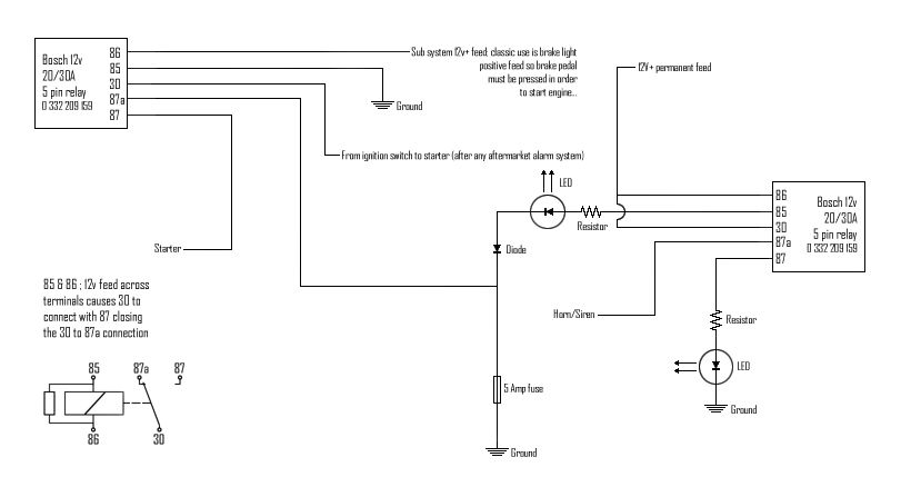
...shows a simple but effective immobilizer, with a twist...
When the vehicle is fired without the subsystem active (i.e. without the brake lights on) the fuse should pop and the second relay is DEACTIVATED, the horn will then sound until the relay is pulled then the fuse replaced, and the relay reinstalled. The LED's installed will give a visual indication of the system status... the LED on the left should be green (or blue if you prefer) and the LED on the right must be red. The red LED is for testing, so the horn/siren can be wired last... as I'm sure you don't want the horn blaring while you reset the setup.
You could be really sneaky and connect the 5 amp fuse into pin 85 on another relay and 86 to an earth point then splice the positive feed into the lambda sensor to pins 30 and 87 so the fuse failure forces limp home mode (not sure thou as it's 3:30am and I'm too tired to find the Haynes...). Anyway you get the picture, a circuit that requires power and is essential for the car to run/run correctly...
The diode must be able to cope with 30A .
The resistors are there purely to drop the voltage for the LED's so choose suitably rated ones.
Install the circuit with the fuse and relay (the one on the right of the diagram) in a hidden but accessible place.