Wiring diagrams or electrics information thread - Discussion
Moderator: Robsey
-
Telegram Sam
- Registered user
- Posts: 1134
- Joined: Tue Mar 13, 2012 7:03 pm
- Location: Brigadoon (Co Durham)
Motronic M4.1 Wiring Info 20SEH
Somewhere on the forum there must be a downloadable basic circuit wiring diagram for the SRi 20 SEH. Could someone kindly show me where? Tks.
'91 H-reg SRi "130" manual hatch 8-valve non cat with mods
Motronic M4.1 Wiring Info 20SEH
There isn't a 20SEH pin out on the forum,
But there is a pin out of my C20NE.
Very similar layout overall. Both use the same pin out.
Just disregard anything referring to the Lambda Sensor or catalyst as the SEH never had either.
viewtopic.php?f=70&t=6685
pin out is on the last post... last item.
EDIT - THE C20NE IN THE LINKED THREAD IS A 1993 MODEL M1.5 AND SO IS NOT THE SAME AS THE EARLY M4.1
ALL INFO IS DETAILED IN THIS THREAD.
-
Telegram Sam
- Registered user
- Posts: 1134
- Joined: Tue Mar 13, 2012 7:03 pm
- Location: Brigadoon (Co Durham)
Motronic M4.1 Wiring Info 20SEH
Tks just what the doctor ordered for those that can understand these things.
'91 H-reg SRi "130" manual hatch 8-valve non cat with mods
Motronic M4.1 Wiring Info 20SEH
Being an SEH, I have made the assumption that your car is a 1989 / 1990 or very early 1991 model.
Later versions of Motronic have a lot more pins in the main connector. 55 from memory. As you can see version 4.1 has a lot fewer.
Later versions of Motronic have a lot more pins in the main connector. 55 from memory. As you can see version 4.1 has a lot fewer.
-
Telegram Sam
- Registered user
- Posts: 1134
- Joined: Tue Mar 13, 2012 7:03 pm
- Location: Brigadoon (Co Durham)
Motronic M4.1 Wiring Info 20SEH
Your assumptions are remarkably accurate. Could you pls "link" me to your C20NE pin out which I seem to have lost. If come the event I can give both to an auto electrician then that should cover most of the basics.
'91 H-reg SRi "130" manual hatch 8-valve non cat with mods
Motronic M4.1 Wiring Info 20SEH
The link is in one of the posts above, however my pin out is for a 1993 C20NE (Motronic ML1.5) with a 55 pin connector.
So not much cop for a 1989 / 1990 car with a smaller connector as fitted to a Motronic ML4.1 system.
So not much cop for a 1989 / 1990 car with a smaller connector as fitted to a Motronic ML4.1 system.
-
Telegram Sam
- Registered user
- Posts: 1134
- Joined: Tue Mar 13, 2012 7:03 pm
- Location: Brigadoon (Co Durham)
Motronic M4.1 Wiring Info 20SEH
Haynes Manual to the rescue I suppose?
'91 H-reg SRi "130" manual hatch 8-valve non cat with mods
Motronic M4.1 Wiring Info 20SEH
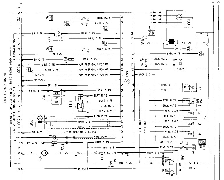
The schematic shown above IS from Haynes and is for the early ML4.1 20SEH.
My pin out in the link is not.
My pin out in the link is not.
-
Telegram Sam
- Registered user
- Posts: 1134
- Joined: Tue Mar 13, 2012 7:03 pm
- Location: Brigadoon (Co Durham)
Motronic M4.1 Wiring Info 20SEH
So hopefully the Haynes would include the corresponding pin out also to complete the picture?
'91 H-reg SRi "130" manual hatch 8-valve non cat with mods
Motronic M4.1 Wiring Info 20SEH
Nope -
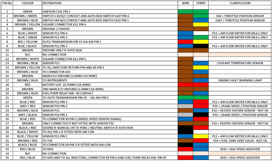
All pin out tables that you find on this site and many other Vauxhall forums are produced by me.
Almost all are by me if they look like an Excell spreadsheet.
I can easily create a pin out by looking at the schematic and transposing the information.
Haynes never did pin outs.
All pin out tables that you find on this site and many other Vauxhall forums are produced by me.
Almost all are by me if they look like an Excell spreadsheet.
I can easily create a pin out by looking at the schematic and transposing the information.
Haynes never did pin outs.
-
Telegram Sam
- Registered user
- Posts: 1134
- Joined: Tue Mar 13, 2012 7:03 pm
- Location: Brigadoon (Co Durham)
Motronic M4.1 Wiring Info 20SEH
Looks like I'm going to be in debt to you for a "bespoke" Jan 91 20 SEH pin out please. Strikes me as a bit of a no-brainer to equip oneself, with our kind of vehicles, with one of these as part of one's emergency toolkit. Especially as the wiring diagram print quality wasn't that brill in spite of my toying about with it.
'91 H-reg SRi "130" manual hatch 8-valve non cat with mods
Motronic M4.1 Wiring Info 20SEH
This is the 1989 and 1990 Motronic ML4.1 pin-out.
It is very different to the later versions of the SEH set up.
That is the 1991 onward version which uses Motronic ML1.5
As yours is registered in January 1991, I would hope that it was still manufactured in late 1990 and therefore this pin-out should be correct.
As for ease of reading - try reading the schematic in night mode - so much easier to see / read.
-
Telegram Sam
- Registered user
- Posts: 1134
- Joined: Tue Mar 13, 2012 7:03 pm
- Location: Brigadoon (Co Durham)
Motronic M4.1 Wiring Info 20SEH
Tks - could be a lifesaver!
'91 H-reg SRi "130" manual hatch 8-valve non cat with mods
Motronic M4.1 Wiring Info 20SEH
Not sure it could be that serious, but you are welcome all the same.Telegram Sam wrote:Tks - could be a lifesaver!
Re: Wiring diagrams or electrics information thread - Discus
Here is an article from a Dutch website about the 4.1 set-up.
The link for the actual page is here..
https://www.squadra-tuning.nl/techniek/ ... iesysteem/
And here is the English translation as my Dutch is not very good.
Bosch Motronic injection system
A bit of history
In the late 1980s the injection system made its appearance in the automotive industry.
Before that time there was already a lot of experimenting in motorsport.
These were mechanically controlled injection systems.
We also encountered these systems at Alfa Romeo.
The best known are the American versions of the old Spider and Montreal.
The German company Bosch was at the forefront of the development of petrol injection systems.
The first mechanically / hydraulically controlled injection system was the K-jetronic system from Bosch.
The injectors continuously injected in front of the intake valves.
An electronic evolution of this system came a little later. The KE jetronic.
The development continued which led to the L-jetronic system. This system injected the fuel pulsing and used a so-called air weigher. (Air mass meter)
An extension to this was the L3, LE, LU, and LH-jetronic system.
The mono-jetronic system was developed for smaller engines. Only one injector for the gas valve.
All previous systems had a separate regulation for the ignition.
Then mechanically / pneumatically or electronically. Of course, it could not fail to unite the two most important devices of the petrol engine in an electronic system.
This is how the Motronic injection system came into being.
Both the ignition and the injection are controlled in a control unit (ECU, Electronic Control Unit).
Around 1984, the Alfa Romeo production cars first became acquainted with the Bosch Motronic injection system in the Alfetta 2.0 Motronic. Moments later, the 90 2.0 Motronic followed and a little later the system was found on almost all Alfa Romeos. This article is about the Bosch Motronic system. How does the system calculate its injection time and pre-ignition? Which sensors are used and how do they ensure the corrections? The oldest and newest Motronic system is always compared with each other.
The Motronic Injection System
The Bosch Motronic injection system has developed considerably over the years. Here is an overview of the functions of the Motronic ML 4.1 system which can be found on the Alfetta 2.0 Motronic from 1984.
(For the purposes of this post - Used on the Cavalier Mk2 (Ascona-C), Cavalier Mk3 (Vectra-A), Astra Mk2 (Kadett-E) )
• Control the petrol injection.
• Control the pre-ignition.
• Regulation of the cold start and warm-up phase.
• Control of enrichment during acceleration.
• Adjust the idling speed.
• Limiting the maximum speed.
• Interruption of the injection of braking on the engine.
• Adjustment of the inlet camshaft.
• Self-diagnosis.
• Driving tachometer.
To control all the above functions, the Motronic system requires a number of sensors. For the Motronic ML 4.1:
• Speed sensor.
• Air quantum meter.
• Motor temperature transmitter.
• Air temperature transmitter.
• Zero-load throttle switch.
• Full load throttle switch.
How does the system get its injection time and pre-ignition, the two most important tasks?
Before I explain that point by point, it is important to know that all values are stored in a programmable memory called the EPROM. This stands for Erasable Programmable Read Only Memory. This has also developed over the years. In the latter systems are so-called FLASH memories that can be programmed from outside the ECU. However, the form in which all values have been programmed has remained the same, in the lines and fields. In other words, 2- and 3-dimensional graphs.
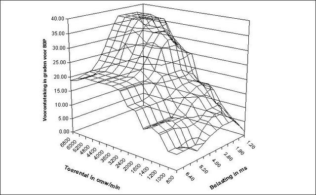
The translation of the graphical legends as far as I can get google to translate them are: -
toerential in omw/min = "rotational " in revolutions per min
belasting in ms = "tax" (??) in milliseconds - I presume injector pulse width in milliseconds
voorontsteking in graden voor bdp = "forinflammation)" injection timing in degrees before top dead centre.
Above you can see a graphical representation of such a ken field. The X and Y axes always show the values of the sensors (speed, water temperature, etc.). On the Z-axis the controlled value for the actuators. There are also conversion tables. Here the result (Z axis) is used again for an X or Y axis. Together, about 150 graphs are stored in an average Motronic system.
In the next section we assume the Motronic ML 4.1 system.
Calculation of the injection time
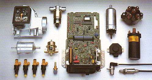
The ECU determines the so-called basic injection time on the basis of the airflow meter (top left of the photo) and the speed. This basic injection time also applies directly as a load on the engine. The load is a quantity that in many other fields is used as the input parameter. When the basic injection time has been determined, a number of corrections will follow in order to arrive at the actually controlled time for the injector. These are discussed below one by one.
Battery (onboard) voltage
The lower the battery (onboard) voltage, the longer it takes for the injector to actually open. An injector is an electromagnetic component. It therefore takes time and electrical power to open it. Once the injector is open, it nebulizes the fuel. Closing also takes time, which is also taken into account.
Coolant temperature
This is particularly important in the warm-up phase. The colder the engine the more fuel is injected.
Inlet temperature
This correction is not as great as the coolant temperature. This is particularly important at very cold starts and the warm-up phase.
Position of the gas valve
The 4.1 system has three variations. Zero load (closed throttle) or stationary position, part load and full load (full throttle). A correction factor is applied depending on the position. These fields are determined experimentally. By going through all possible operating conditions, the basic injection time is corrected to a real injection time that produces a nicely running engine that meets the set requirements.
Accelerate / decelerate
The injection is of course also adjusted for acceleration and deceleration. To start with the last one I think it is obvious that the injection is interrupted when the accelerator is released. However, this must recognize the ECU as such. He does this on the basis of the speed and the no-load switch. If it is closed and the speed is above a certain value, the ECU recognizes that as a brake on the engine. As soon as the speed comes close to the aforementioned limit, the injection is started again to prevent the engine from turning off. This phenomenon is described with the term "fuel cut-off". Something similar applies to the acceleration but then, as it were, exactly the other way around. The ECU looks at the speed at which the accelerator pedal is pressed. He does this on the basis of the airflow meter.
Before I explain how that works, it is important to know how the airflow meter works. There is a kind of stowage door in the airflow meter. This door is pulled open or pushed by the air drawn in by the intake air of the engine. When suddenly accelerating, the airflow meter will also suddenly open. The speed of opening is a measure of acceleration. In the EPROM, a characteristic line has been included in which this speed is plotted against the enrichment factor. When the speed of opening is zero, no more is enriched.
Speed limiter
The Motronic 4.1 system has two speed limiters . If this is exceeded, the fuel injection will be stopped. The first speed limiter may be exceeded for a certain time. When this time has elapsed, the injection is stopped. The second limiter is a few hundred rpm higher. When this is exceeded, the injection is stopped immediately. An example. The 6300 speed limit may be exceeded for 1.5 seconds. At 6600 rpm there is immediate intervention.
Calculation of the pre-ignition
For the determination of the pre-ignition, virtually the same corrections apply. On the basis of the speed and the air quantity, the "on time" of the ignition coil is determined first, the charging time of the ignition coil. As soon as the ignition coil is switched off, a spark occurs as a result of the induction effect of the ignition coil. Subsequently, corrections are made again.
Coolant temperature
Especially in the warm-up phase it is important. The ignition is then brought forward at a lower coolant temperature.
Inlet temperature
The same correction applies here as in the coolant temperature. However, the correction is not that great. When conditions arise where both the intake air temperature and the coolant temperature reach very high values, the ignition will be extra empty. This is to prevent pinging (uncontrolled combustion) of the engine. This situation occurs, for example, by slowly ascending a steep slope with a caravan in the summer. This means that some power is surrendered. A later ignition means namely loss of power.
Throttle position
The system has separate ignition fields for idling, partial load and full load, just as before the injection time. These too have been determined experimentally. This makes it possible to give the engine a certain running culture or character. As described in an earlier article about torque and power, the ignition sequence determines a large part of the available torque. One can hereby influence the character of an engine whereby sometimes concessions are made with respect to the maximum possible available torque. Here lies the working area of the chipper.
Accelerate / decelerate
The ignition is also corrected when it comes to accelerating and decelerating. When accelerating, there is a loss of ignition to make the engine easier to speed up. When decelerating, the ignition is adjusted in such a way that the fuel cut-off is less frequent in combination with the stopping of the injection. With automatic gearboxes or Selespeed, the ignition is adjusted to make the switch more smooth.
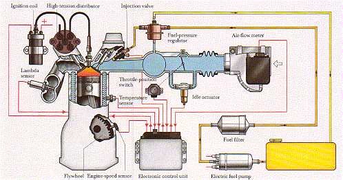
Schematic overview M4.1 system
In addition to the control of the injection and ignition there are also a number of additional functions.
Idle speed control
The idle speed is controlled with a circulation around the throttle. The amount of air that is sent through this channel around the gas valve is controlled by the ECU with the help of an electromagnetic valve. The stationary speed is programmed in the memory of the ECU. The idling speed is mainly dependent on the engine temperature. The lower the temperature, the higher the speed. It is a so-called control system. If the engine runs at 600 revolutions per minute and is in the memory that the engine should run 950, the idle regulator is controlled more. Then there is more air coming in which makes the engine run faster.
Camshaft positioner
This is adjusted from certain combinations of speeds and loads. The adjustment takes place by opening an electromagnetic valve which in turn sets oil pressure on the camshaft adjuster and thus adjusts. When the camshaft adjustment is active, other fields are used for injection and ignition.
Self-diagnosis
The first Motronic system hardly had any self-diagnosis. He could only recognize and display a limited number of errors. This was shown by a blink code that could be activated by connecting two pins of the ECU to each other. A light that showed a blink code was connected via another pin on the ECU.
I have edited the remainder of the document out, as it refers to later closed loop emissions sytems and diagnostics that are not relevant on the Cavalier.
Please also excuse the translation - this is a Google / Bing translation, so some phrases or key words may not make perfect sense in English.
The link for the actual page is here..
https://www.squadra-tuning.nl/techniek/ ... iesysteem/
And here is the English translation as my Dutch is not very good.
Bosch Motronic injection system
A bit of history
In the late 1980s the injection system made its appearance in the automotive industry.
Before that time there was already a lot of experimenting in motorsport.
These were mechanically controlled injection systems.
We also encountered these systems at Alfa Romeo.
The best known are the American versions of the old Spider and Montreal.
The German company Bosch was at the forefront of the development of petrol injection systems.
The first mechanically / hydraulically controlled injection system was the K-jetronic system from Bosch.
The injectors continuously injected in front of the intake valves.
An electronic evolution of this system came a little later. The KE jetronic.
The development continued which led to the L-jetronic system. This system injected the fuel pulsing and used a so-called air weigher. (Air mass meter)
An extension to this was the L3, LE, LU, and LH-jetronic system.
The mono-jetronic system was developed for smaller engines. Only one injector for the gas valve.
All previous systems had a separate regulation for the ignition.
Then mechanically / pneumatically or electronically. Of course, it could not fail to unite the two most important devices of the petrol engine in an electronic system.
This is how the Motronic injection system came into being.
Both the ignition and the injection are controlled in a control unit (ECU, Electronic Control Unit).
Around 1984, the Alfa Romeo production cars first became acquainted with the Bosch Motronic injection system in the Alfetta 2.0 Motronic. Moments later, the 90 2.0 Motronic followed and a little later the system was found on almost all Alfa Romeos. This article is about the Bosch Motronic system. How does the system calculate its injection time and pre-ignition? Which sensors are used and how do they ensure the corrections? The oldest and newest Motronic system is always compared with each other.
The Motronic Injection System
The Bosch Motronic injection system has developed considerably over the years. Here is an overview of the functions of the Motronic ML 4.1 system which can be found on the Alfetta 2.0 Motronic from 1984.
(For the purposes of this post - Used on the Cavalier Mk2 (Ascona-C), Cavalier Mk3 (Vectra-A), Astra Mk2 (Kadett-E) )
• Control the petrol injection.
• Control the pre-ignition.
• Regulation of the cold start and warm-up phase.
• Control of enrichment during acceleration.
• Adjust the idling speed.
• Limiting the maximum speed.
• Interruption of the injection of braking on the engine.
• Adjustment of the inlet camshaft.
• Self-diagnosis.
• Driving tachometer.
To control all the above functions, the Motronic system requires a number of sensors. For the Motronic ML 4.1:
• Speed sensor.
• Air quantum meter.
• Motor temperature transmitter.
• Air temperature transmitter.
• Zero-load throttle switch.
• Full load throttle switch.
How does the system get its injection time and pre-ignition, the two most important tasks?
Before I explain that point by point, it is important to know that all values are stored in a programmable memory called the EPROM. This stands for Erasable Programmable Read Only Memory. This has also developed over the years. In the latter systems are so-called FLASH memories that can be programmed from outside the ECU. However, the form in which all values have been programmed has remained the same, in the lines and fields. In other words, 2- and 3-dimensional graphs.
The translation of the graphical legends as far as I can get google to translate them are: -
toerential in omw/min = "rotational " in revolutions per min
belasting in ms = "tax" (??) in milliseconds - I presume injector pulse width in milliseconds
voorontsteking in graden voor bdp = "forinflammation)" injection timing in degrees before top dead centre.
Above you can see a graphical representation of such a ken field. The X and Y axes always show the values of the sensors (speed, water temperature, etc.). On the Z-axis the controlled value for the actuators. There are also conversion tables. Here the result (Z axis) is used again for an X or Y axis. Together, about 150 graphs are stored in an average Motronic system.
In the next section we assume the Motronic ML 4.1 system.
Calculation of the injection time
The ECU determines the so-called basic injection time on the basis of the airflow meter (top left of the photo) and the speed. This basic injection time also applies directly as a load on the engine. The load is a quantity that in many other fields is used as the input parameter. When the basic injection time has been determined, a number of corrections will follow in order to arrive at the actually controlled time for the injector. These are discussed below one by one.
Battery (onboard) voltage
The lower the battery (onboard) voltage, the longer it takes for the injector to actually open. An injector is an electromagnetic component. It therefore takes time and electrical power to open it. Once the injector is open, it nebulizes the fuel. Closing also takes time, which is also taken into account.
Coolant temperature
This is particularly important in the warm-up phase. The colder the engine the more fuel is injected.
Inlet temperature
This correction is not as great as the coolant temperature. This is particularly important at very cold starts and the warm-up phase.
Position of the gas valve
The 4.1 system has three variations. Zero load (closed throttle) or stationary position, part load and full load (full throttle). A correction factor is applied depending on the position. These fields are determined experimentally. By going through all possible operating conditions, the basic injection time is corrected to a real injection time that produces a nicely running engine that meets the set requirements.
Accelerate / decelerate
The injection is of course also adjusted for acceleration and deceleration. To start with the last one I think it is obvious that the injection is interrupted when the accelerator is released. However, this must recognize the ECU as such. He does this on the basis of the speed and the no-load switch. If it is closed and the speed is above a certain value, the ECU recognizes that as a brake on the engine. As soon as the speed comes close to the aforementioned limit, the injection is started again to prevent the engine from turning off. This phenomenon is described with the term "fuel cut-off". Something similar applies to the acceleration but then, as it were, exactly the other way around. The ECU looks at the speed at which the accelerator pedal is pressed. He does this on the basis of the airflow meter.
Before I explain how that works, it is important to know how the airflow meter works. There is a kind of stowage door in the airflow meter. This door is pulled open or pushed by the air drawn in by the intake air of the engine. When suddenly accelerating, the airflow meter will also suddenly open. The speed of opening is a measure of acceleration. In the EPROM, a characteristic line has been included in which this speed is plotted against the enrichment factor. When the speed of opening is zero, no more is enriched.
Speed limiter
The Motronic 4.1 system has two speed limiters . If this is exceeded, the fuel injection will be stopped. The first speed limiter may be exceeded for a certain time. When this time has elapsed, the injection is stopped. The second limiter is a few hundred rpm higher. When this is exceeded, the injection is stopped immediately. An example. The 6300 speed limit may be exceeded for 1.5 seconds. At 6600 rpm there is immediate intervention.
Calculation of the pre-ignition
For the determination of the pre-ignition, virtually the same corrections apply. On the basis of the speed and the air quantity, the "on time" of the ignition coil is determined first, the charging time of the ignition coil. As soon as the ignition coil is switched off, a spark occurs as a result of the induction effect of the ignition coil. Subsequently, corrections are made again.
Coolant temperature
Especially in the warm-up phase it is important. The ignition is then brought forward at a lower coolant temperature.
Inlet temperature
The same correction applies here as in the coolant temperature. However, the correction is not that great. When conditions arise where both the intake air temperature and the coolant temperature reach very high values, the ignition will be extra empty. This is to prevent pinging (uncontrolled combustion) of the engine. This situation occurs, for example, by slowly ascending a steep slope with a caravan in the summer. This means that some power is surrendered. A later ignition means namely loss of power.
Throttle position
The system has separate ignition fields for idling, partial load and full load, just as before the injection time. These too have been determined experimentally. This makes it possible to give the engine a certain running culture or character. As described in an earlier article about torque and power, the ignition sequence determines a large part of the available torque. One can hereby influence the character of an engine whereby sometimes concessions are made with respect to the maximum possible available torque. Here lies the working area of the chipper.
Accelerate / decelerate
The ignition is also corrected when it comes to accelerating and decelerating. When accelerating, there is a loss of ignition to make the engine easier to speed up. When decelerating, the ignition is adjusted in such a way that the fuel cut-off is less frequent in combination with the stopping of the injection. With automatic gearboxes or Selespeed, the ignition is adjusted to make the switch more smooth.
Schematic overview M4.1 system
In addition to the control of the injection and ignition there are also a number of additional functions.
Idle speed control
The idle speed is controlled with a circulation around the throttle. The amount of air that is sent through this channel around the gas valve is controlled by the ECU with the help of an electromagnetic valve. The stationary speed is programmed in the memory of the ECU. The idling speed is mainly dependent on the engine temperature. The lower the temperature, the higher the speed. It is a so-called control system. If the engine runs at 600 revolutions per minute and is in the memory that the engine should run 950, the idle regulator is controlled more. Then there is more air coming in which makes the engine run faster.
Camshaft positioner
This is adjusted from certain combinations of speeds and loads. The adjustment takes place by opening an electromagnetic valve which in turn sets oil pressure on the camshaft adjuster and thus adjusts. When the camshaft adjustment is active, other fields are used for injection and ignition.
Self-diagnosis
The first Motronic system hardly had any self-diagnosis. He could only recognize and display a limited number of errors. This was shown by a blink code that could be activated by connecting two pins of the ECU to each other. A light that showed a blink code was connected via another pin on the ECU.
I have edited the remainder of the document out, as it refers to later closed loop emissions sytems and diagnostics that are not relevant on the Cavalier.
Please also excuse the translation - this is a Google / Bing translation, so some phrases or key words may not make perfect sense in English.
-
Telegram Sam
- Registered user
- Posts: 1134
- Joined: Tue Mar 13, 2012 7:03 pm
- Location: Brigadoon (Co Durham)
Re: Wiring diagrams or electrics information thread - Discus
Tks - have added this to my survival kit. I am impressed by your (technical) Dutch.
'91 H-reg SRi "130" manual hatch 8-valve non cat with mods
Re: Wiring diagrams or electrics information thread - Discus
Ha ha -
It isn't my technical Dutch...
It is simply google translate.
That is why the 3 dimensional graph is called a "ken" rather than a map.
Looks more like a harry to me, but hey ho.
It isn't my technical Dutch...
It is simply google translate.
That is why the 3 dimensional graph is called a "ken" rather than a map.
Looks more like a harry to me, but hey ho.