COMFORT CLOSURE CIRCUIT.
I have not tried it myself, but a friend on the OpCom forum has fitted this to a Zafira-A with good working results.
The pin numbers, functions and wire colours do seem to correlate between the different vehicles.
These are very basic circuits, using just resistors, transistors, a diode and capacitors, so none of that fiddley SMD rubbish.
Others have suggested using a 555 timer circuit, but hey - lets keep it simple.
There are two circuits -
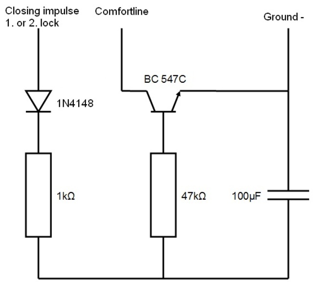
A simple one for full closure on one press of the fob lock button.
Circuit here -
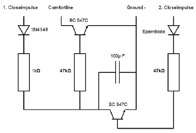
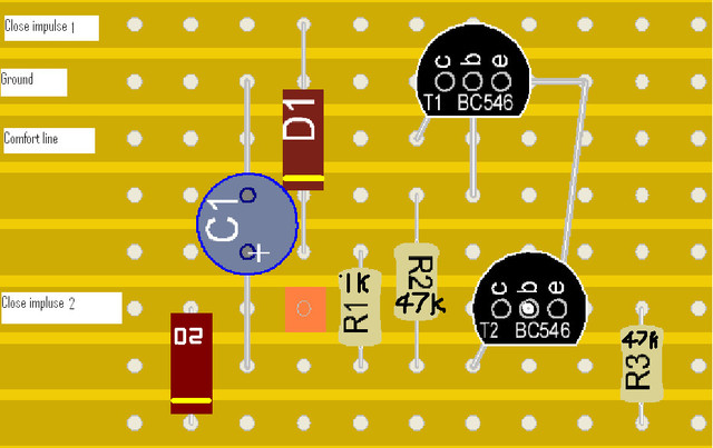
A second one with closure on one button press, but then stop the windows upon the second press of the button.
With stop function
Pro: If you have pets then this function can help to leave the windows open if needed
Con: You have always to wait until window closes completely before you activate the second lock.
Circuit here-
Hint: If you have a powered Omega one-touch sun roof you normally need to change the capacitor from 100µF to 470µF.
Please use a 220uF cap instead of the listed 100uF cap when your car has only 2 elec. windows if it has more windows then use the 470uF cap.
INFORMATION - for anyone wanting to make this circuit, the Cathode of the Capacitor goes to ground.
What to do.
1 - Make the circuit of your choice.
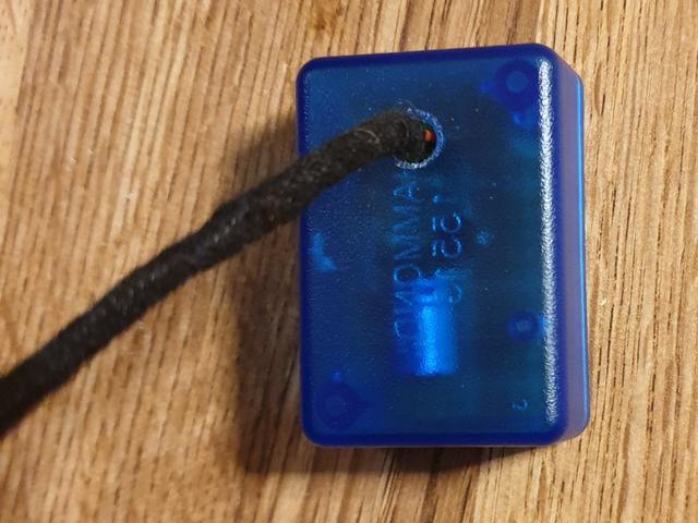
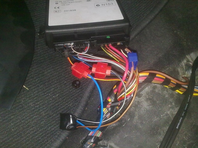
2 - Locate the Vectra-B remote central locking module, and a good ground point. The images here clearly show a Zafira-A Bosch unit.
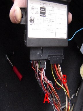
3 - Connect the wires to the module - please do not use scotch-locks as in this image.
solder and heat shrink tubing please...
Wires are -
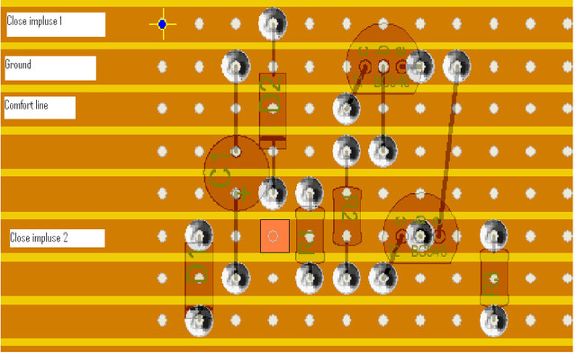
Close impulse 1 = right connector (B) (Pin 7, black/yellow)
Close impulse 2 = left connector (A) (Pin 10, blue/black)
Comfort Closure / Window Lifter = left connector (A) (Pin 24 red/yellow or brown/black depends on model year)
Ground point = hopefully quite obvious.
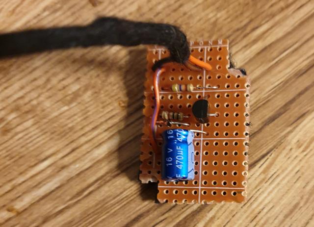
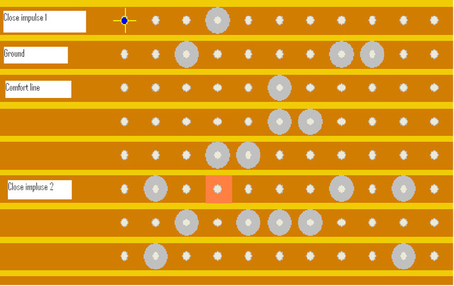
Here is the 2nd circuit using Vero-board / strip board.
Good luck and happy closures.
Here is a final comment by Mark. -
When I wired mine to the car this is how I wired it:-
My car was a late 2000 Zafira-A with Z16XE engine
Close Impulse 1 went to Black/Yellow which is Pin 7 (Connector B)
Close Impulse 2 went to Blue/Black which is Pin 10 (Connector A)
Comfort went to Brown/Black which is Pin 24 (Connector A)
Ground went direct to the cars grounding bolt.
Always check pin numbers and wire colours before wiring as they do differ sometimes. Pin numbers are the same for Astra G and Zafira A but wire colours MAY differ.
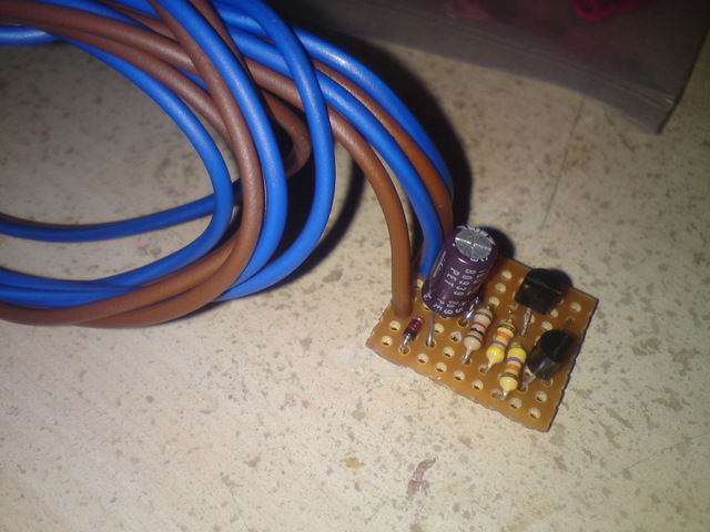
The pcb made up ready.
Thanks to Mark and Ducky from the OpComusers forum for the original information and images.